Floor bearing pressure testing device for constructional engineering

A pressure testing and construction engineering technology, applied in measuring devices, using stable tension/pressure testing materials, instruments, etc., can solve the problems of low efficiency of testing pressure operation, cumbersome operation steps, inconvenient use, etc., to achieve adjustment and use The operation is convenient and quick, the steps and processes are simplified, and the operation is convenient and labor-saving and quick.

Inactive Publication Date: 2020-06-19
陈欣
View PDF1 Cites 2 Cited by
  • Summary
  • Abstract
  • Description
  • Claims
  • Application Information

AI Technical Summary

Problems solved by technology

[0005] The purpose of the present invention is to provide a load-bearing pressure test device for floor slabs used in construction engineering to solve the cumbersome operation steps and inconvenient use proposed in the above background technology, and the gravity pressing blocks mostly use bricks or lead blocks to stack and counterweight. When reducing and adjusting the test force, it is necessary to repeatedly move the bricks or lead blocks, which is laborious, resulting in the problem of low operational efficiency in the adjustment of the test pressure.

Method used


Image

  • Floor bearing pressure testing device for constructional engineering
  • Floor bearing pressure testing device for constructional engineering
  • Floor bearing pressure testing device for constructional engineering

Examples


Embodiment Construction

[0028] The following will clearly and completely describe the technical solutions in the embodiments of the present invention with reference to the accompanying drawings in the embodiments of the present invention. Obviously, the described embodiments are only some of the embodiments of the present invention, not all of them.

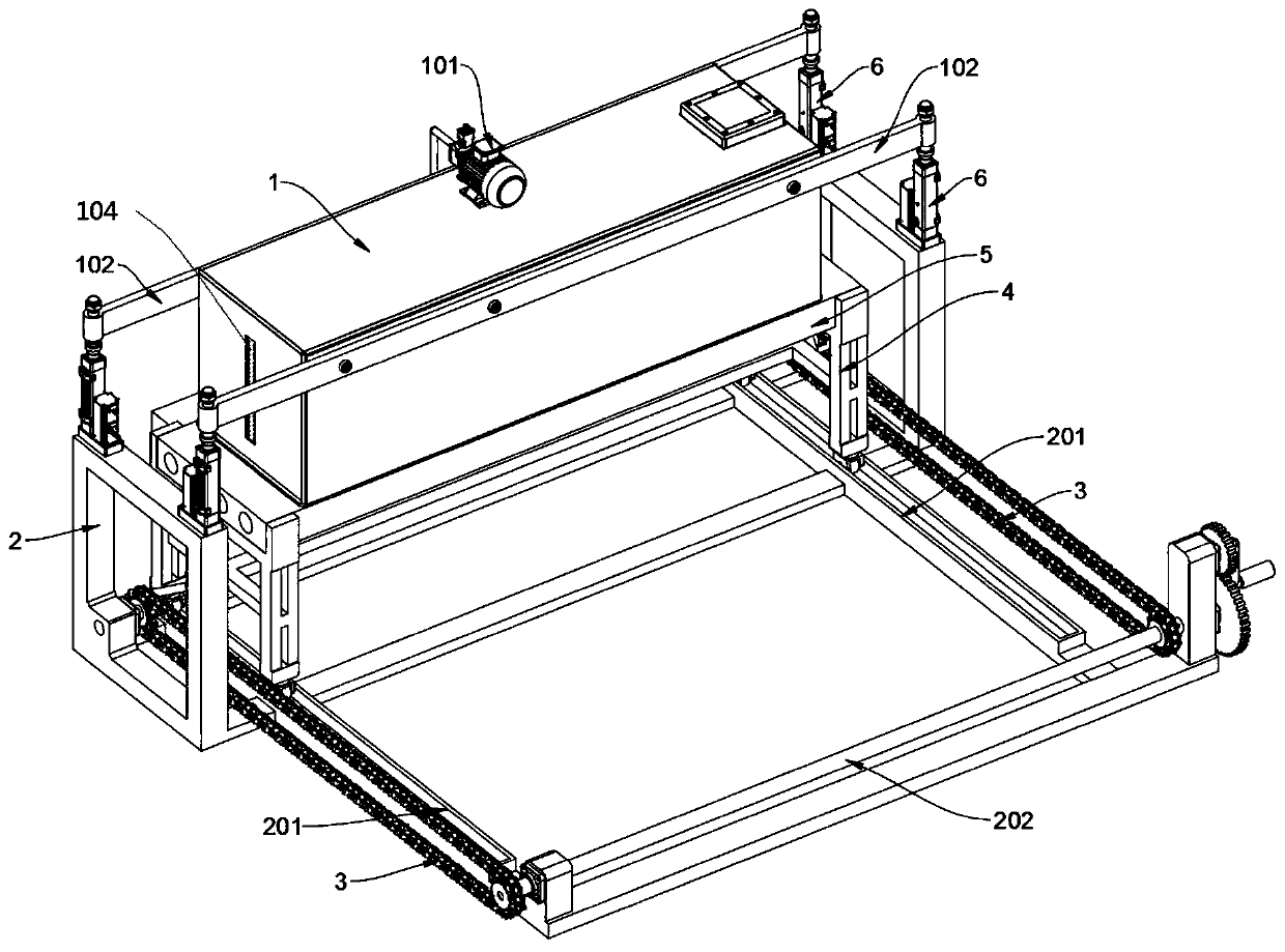
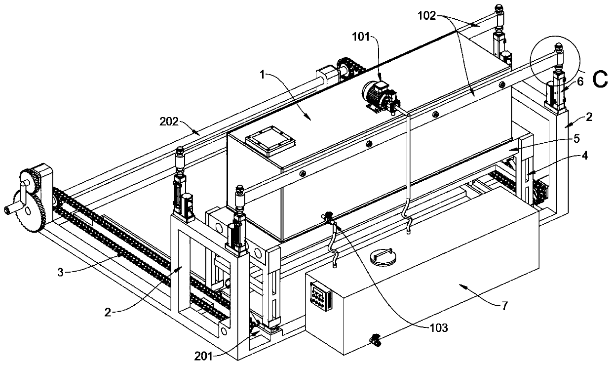
[0029] see Figure 1 to Figure 9 , an embodiment provided by the present invention: a floor load-bearing pressure test device for construction engineering, including a heavy-pressure water tank 1, a test bracket 2 and a floor truck 4, the heavy-pressure water tank 1 includes a replenishment pump 101, a cross-bracing support plate 102, Drain pipe 103 and strip glass window 104, the middle place of heavy pressure water tank 1 left side wall is inlaid with a strip glass window 104, and water level scale is printed on this strip glass window 104, and the top of heavy pressure water tank 1 There is a supplementary water pump 101 locked in the middle, and the...


PUM


Abstract

The invention discloses a floor bearing pressure testing device for constructional engineering, relates to the technical field of floor testing equipment, and solves the problems that an existing bearing pressure testing device is tedious in operation step, inconvenient to use and low in efficiency of adjustment of testing pressure. The floor bearing pressure testing device for constructional engineering comprises a heavy pressure water tank and a floor vehicle, two transverse supporting plates are symmetrically locked and fixed to the front side and the rear side of the top end of the heavy pressure water tank, and piston rods of four electric push rods on the left side and the right side correspondingly penetrate through four shaft sleeves at the two ends of the two transverse supportingplates; the four electric push rods are symmetrically locked and vertically supported at the top ends of left and right supporting square frames of a test support, and a rectangular water supplementing tank is further welded and fixed to the rear side of the test support. When the weight of the heavy-pressure water tank is adjusted, the water level can be observed through a long-strip-shaped glass window, the weight of water stored in the heavy-pressure water tank is converted according to the density of water, and convenience is provided for weight adjustment of the heavy-pressure water tank.

Description

technical field [0001] The invention relates to the technical field of floor slab testing equipment, in particular to a load-bearing pressure testing device for floor slabs used in construction engineering. Background technique [0002] Concrete prefabricated components are building components prefabricated in factories with concrete and steel bars as the basic materials, including beams, slabs, columns, floor slabs and building decoration accessories. The test is used to detect the quality of the prefabricated components of the floor slab, which requires a load-bearing pressure test device for the floor slab used in construction engineering. [0003] For example, the patent No. CN201820463411.8 discloses an anti-crack detection device for a cast-in-place concrete structure floor, which includes two support columns, the tops of which are fixedly connected with connecting rods, and the connecting rods are slidably connected with a first set of The sleeve and the second sleev...

Claims


Application Information

Patent Timeline
Patent Type & Authority Applications(China)
IPC IPC(8): G01N3/12G01N3/02
CPCG01N3/02G01N3/12G01N2203/0019G01N2203/0048
Inventor 陈欣
Owner 陈欣
Why Eureka
Try Eureka