Capacitance detection apparatus and method

A technology of capacitance detection and capacitance, which is applied in the electronic field and can solve problems such as solution proposals

Active Publication Date: 2009-07-08
TIANJIN SIGMA MICROELECTRONICS CO LTD
View PDF0 Cites 30 Cited by
  • Summary
  • Abstract
  • Description
  • Claims
  • Application Information

AI Technical Summary

Problems solved by technology

[0002] In recent years, capacitive touch sensing technology has been widely used in portable electronics, consumer electronics, notebook computers and other fields. Many technologies such as to

Method used


Image

  • Capacitance detection apparatus and method
  • Capacitance detection apparatus and method
  • Capacitance detection apparatus and method

Examples


Embodiment Construction

[0030] Figure 4 It is a schematic circuit diagram of the capacitance detection device of the present invention. The measured capacitor CT is connected to the power supply Vdd through the first switch S1, one input end of the comparator 41 is connected to the reference voltage Vref, and the other end is connected to the measured capacitor CT. The output signal Vcom of the comparator 41 and a clock signal Vclk2 pass through the logical AND gate 42 to output the signal Vs2. The second switch S2 connects the measured capacitor CT to the integrating capacitor CL. The first switch S1 is controlled by a clock signal Vs1, and the second switch S2 is controlled by a signal Vs2. The comparator 41 will compare the voltage on the measured capacitor CT with the reference voltage at any time.

[0031] like Figure 5 Shown is a set of timing diagrams for capacitance detection using the setup described above.

[0032] In the T1 phase of the first clock cycle, when Vs1 is at a high level...


PUM


Abstract

The invention discloses a capacitance detection device and a capacitance detection method. The device comprises a comparator, an integrating capacitor, and an analog-to-digital converter, wherein the comparator is used for comparing voltage so as to control the discharge time of a measured capacitor; the integrating capacitor is used for integrating the discharge charge of the measured capacitor and producing an integrating voltage which has certain relation with the measured capacitor; and the analog-to-digital converter is used for converting the integrating voltage into corresponding digital quantity. The device and the method can realize higher-accuracy high-speed capacitance detection, and can be used for identifying the capacitance in a resistance-capacitance network and detecting the capacitance; and the characteristic can solve the excessive problem in capacitive touch application.

Description

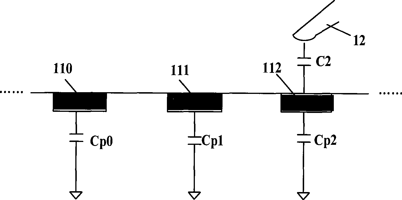
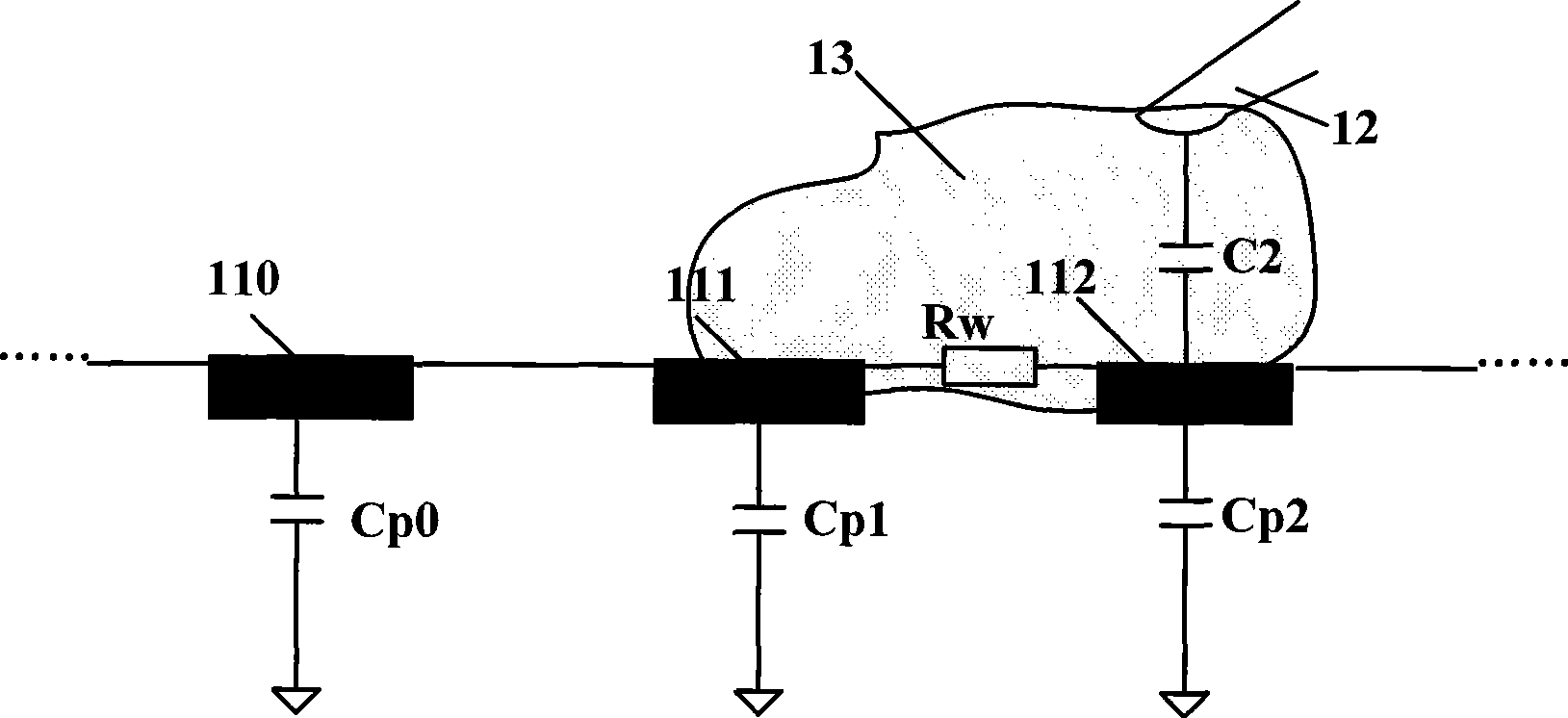
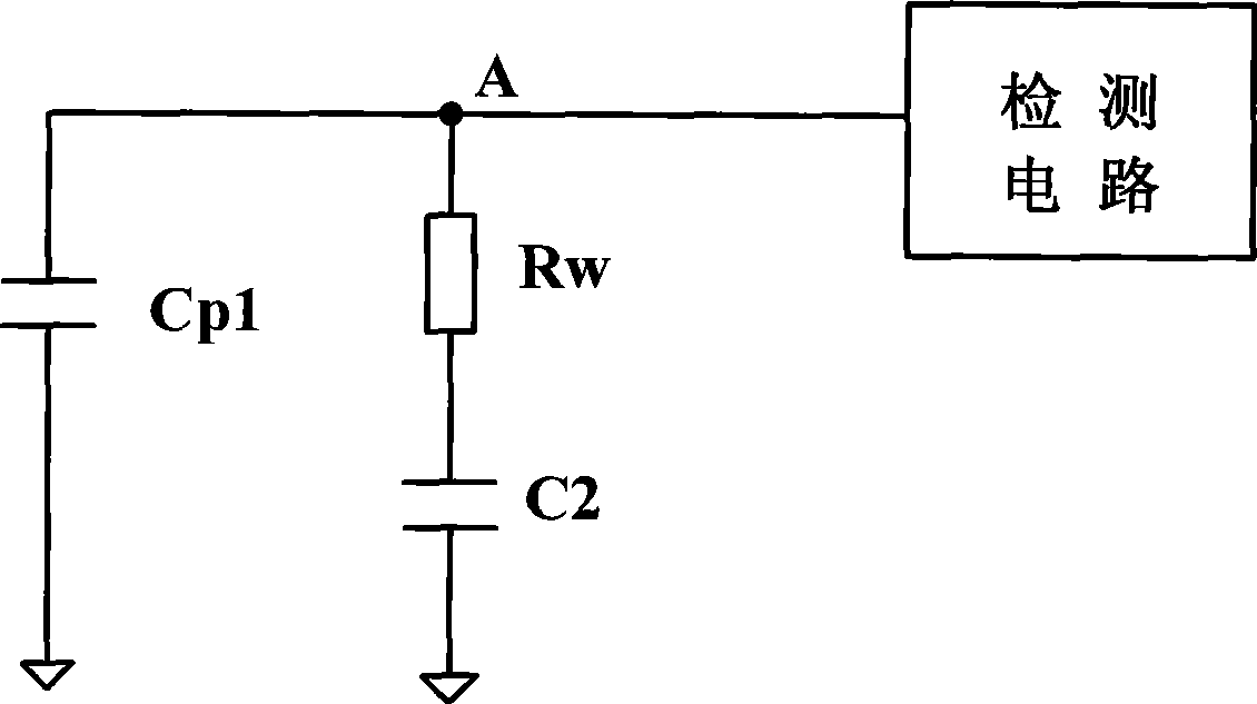
technical field [0001] The invention describes a capacitance detection device and method, which belongs to the field of electronic technology, and in particular relates to a device and method capable of detecting capacitance value in a water-contact state. Background technique [0002] In recent years, capacitive touch sensing technology has been widely used in portable electronics, consumer electronics, notebook computers and other fields. Many technologies such as touch buttons, full-screen touch, and multi-finger touch are also developing rapidly. However, in terms of improving the water resistance of capacitive touch , and no better solution was proposed. [0003] like figure 1 As shown, a capacitive touch sensing device usually includes a certain number of capacitive sensing points (110, 111 or 112...), and each capacitive sensing point has inherent parasitic capacitance (Cp0, Cp1 or Cp2...). For example, when a finger (or other conductor, 12 ) approaches the capaciti...

Claims


Application Information

Patent Timeline
IPC IPC(8): G01R27/26G06F3/044
Inventor 甄志芳李志谦
Owner TIANJIN SIGMA MICROELECTRONICS CO LTD
Why Eureka
Try Eureka