Three-dimension graphics direct-writing method with multi-vision angle graphical input

A technology of three-dimensional graphics and graphic input, which is applied in the direction of instruments, etc., can solve the problems of high technical requirements, high cost, and poor flexibility in the production of color three-dimensional holographic images, and achieve the effect of flexible image input and processing

A technology of three-dimensional graphics and graphic input, which is applied in the direction of instruments, etc., can solve the problems of high technical requirements, high cost, and poor flexibility in the production of color three-dimensional holographic images, and achieve the effect of flexible image input and processing

CN101477326AActive Publication Date: 2009-07-08SVG TECH GRP CO LTD +1

Image

  • Three-dimension graphics direct-writing method with multi-vision angle graphical input
  • Three-dimension graphics direct-writing method with multi-vision angle graphical input
  • Three-dimension graphics direct-writing method with multi-vision angle graphical input

Examples


Embodiment 1

[0049] Embodiment one: see attached image 3 As shown, a three-dimensional graphics direct writing method for multi-view graphics input, the steps are as follows:

[0050] (1) To obtain the sub-viewpoint digital image of a three-dimensional object, it can be taken by a camera, with the object as the center, and taken at certain angles, or computer virtual three-dimensional image processing can be used to obtain the sub-viewpoint image of the virtual object. The image number is from 1 to n, and the image format is not limited.

[0051] (2) Perform red R, green G, and blue B color separation processing on each image, such as Figure 4 As shown, the numbers are R1, G1, B1, R2, G2, B2,..., Rn, Gn, Bn. If the obtained image is a grayscale image, this step can be omitted.

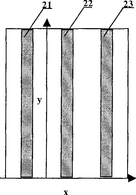
[0052] (3) Divide the above color-separated image to form sub-graphs, such as Figure 5 As shown, the size of each submap is m×m pixels. For example 64×64 pixels.

[0053] (4) if Figure 6 As shown, the fi...

Embodiment 2

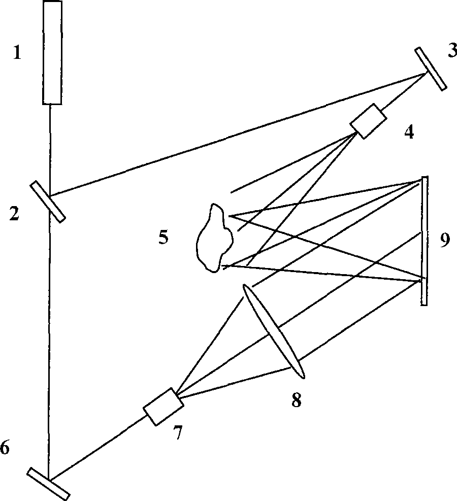
[0057] Embodiment two: see attached Figure 8 As shown, it is an optical path implementation method using an off-axis reflective spatial light modulator. The laser beam 71 passes through the beam splitter 72, and a beam of light is irradiated obliquely on the spatial light modulator 76 after beam expansion and collimation, and the information on the spatial light modulator is read out. The image of the object is reproduced, and the dry plate 78 is placed, and another beam of light passing through the beam splitter interferes with the object light wave on the dry plate 78 after proper beam expansion and collimation. The information on the spatial light modulator is controlled by the computer 712 in real time, and the dry plate and the optical system can move relative to each other in two dimensions within the plane of the dry plate to match the relative positions of the SLM and the dry plate to realize pattern splicing.

[0058] Compared with the traditional two-step method, t...

Embodiment 3

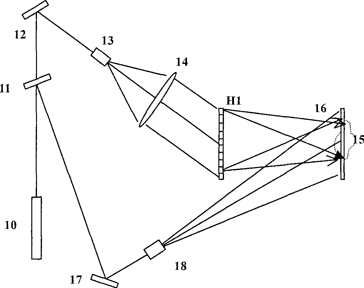
[0061] Embodiment three: see attached Figure 9 As shown, it is an optical path implementation method using a coaxial reflective spatial light modulator. After the laser beam 81 passes through the beam splitter 82, a beam of light is expanded and collimated, then irradiates the spatial light modulator 87 after passing through the beam splitter 86, reads information, and forms on the rear focal plane after passing through the Fourier transform lens 88 As for the image of the object, other processes are the same as in Embodiment 1.


PUM


Abstract

The invention discloses a three-dimensional graph direct writing method for multi-visual angle graphic input, which comprises the following steps: firstly, acquiring sub-visual angle planar digital images of a three-dimensional object; secondly, performing color separation on each image, splitting the image into subgraphs, and forming subgraphs with same corresponding positions in various images into a group; thirdly, acquiring a group of subgraphs, respectively adopting an iterative Fourier transform principle to calculate light field distribution of each subgraph in a far field, extracting phase information, arranging the phase information according to the visual angle, and encoding the phase information into H1; fourthly, using a spatial light modulator to display the H1, laying the H1 on a front focal plane of a lens, forming multi-visual angle image reproduction on a rear focal plane of the lens, introducing interference light, and recording reproduced images on recording materials through an interference light path; fifthly, moving the position of the recording materials corresponding to the position of the next group of subgraphs; and sixthly, repeatedly executing the steps until all the subgraphs are recorded, and realizing recording of a three-dimensional graph. The three-dimensional graph direct writing method uses a mode of laser direct writing to manufacture the three-dimensional graph which has rich information expression characteristic.

Description

technical field [0001] The invention relates to a method for making three-dimensional graphics, in particular to a direct writing method for three-dimensional graphics suitable for plate making of large-format three-dimensional graphics and applicable to three-dimensional display, three-dimensional printing and virtual reality multi-view graphics input. Background technique [0002] When people observe an object, light is reflected from the object to form a wavefront, which propagates in all directions in space. The human eye observes different wavefronts of light from different directions. If the wavefront can be recorded and reproduced , even if the object does not exist, the human eye can still observe the existence of the virtual object. [0003] Traditional holography technology is an effective method to record the wavefront of light. It uses a coherent laser and introduces reference light for interference on the basis of object light to simultaneously record the intens...

Claims


Application Information

Patent Timeline
08 Jul 2009
Publication
CN101477326A
IPC
G03H1/12; G03H1/26
Inventors
陈林森; 浦东林