
Non-contact type electric energy, data integrated sliding ring type transmission method

A transmission method, non-contact technology, applied in transmission systems, near-field transmission systems, electrical components, etc., can solve problems such as inability to transmit electric energy, and achieve the effects of cost reduction, high efficiency, and reduced quantity

Active Publication Date: 2009-07-08
XIDIAN UNIV
View PDF0 Cites 42 Cited by
  • Summary
  • Abstract
  • Description
  • Claims
  • Application Information

AI Technical Summary

Problems solved by technology

However, the photoelectric bus ring requires a precise optical mechanism, and it can only transmit signals but not electric energy.

Method used


Image

  • Non-contact type electric energy, data integrated sliding ring type transmission method
  • Non-contact type electric energy, data integrated sliding ring type transmission method

Examples


Embodiment 1

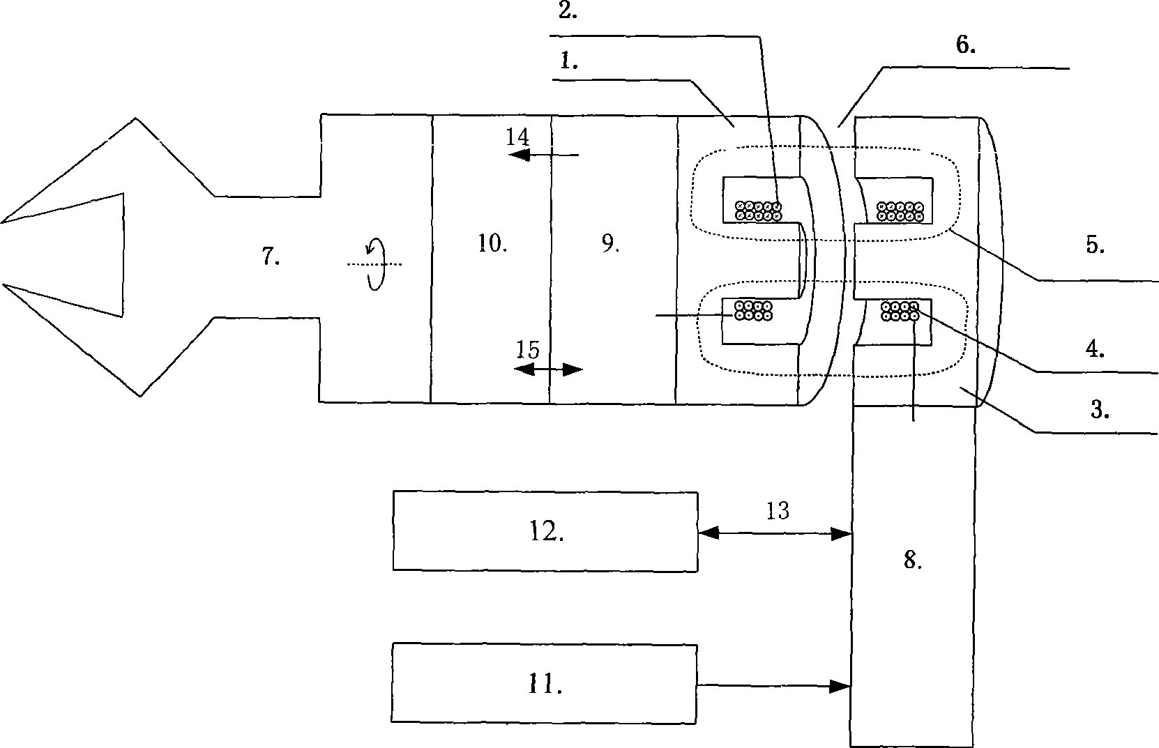
[0038] Embodiment 1 provides an electric energy and signal transmission structure of a coaxial rotary moving part with an air gap. Non-contact power supply and communication applied to mechanical joints.

[0039] like figure 1 As shown, a rotating high-frequency ferrite 1 and a coil 2 are additionally installed on the rotating shaft 7 of the mechanical arm. The rotating high-frequency ferrite 1 is in the shape of a magnetic ring, and the coil 2 is fixed in the rotating high-frequency ferrite 1 in the shape of a magnetic ring. Wherein, the magnetic ring made of rotating high-frequency ferrite 1 rotates with the rotating shaft 7 of the mechanical arm. The fixed high-frequency ferrite 3 body with an air gap 6 left with the rotating high-frequency ferrite 1 is fixed by the foundation, and the fixed high-frequency ferrite 3 is also in the shape of a magnetic ring. The inner magnetic ring formed by the fixed high-frequency ferrite 3 There is a fixed coil 4; the rotating high-freq...

Embodiment 2

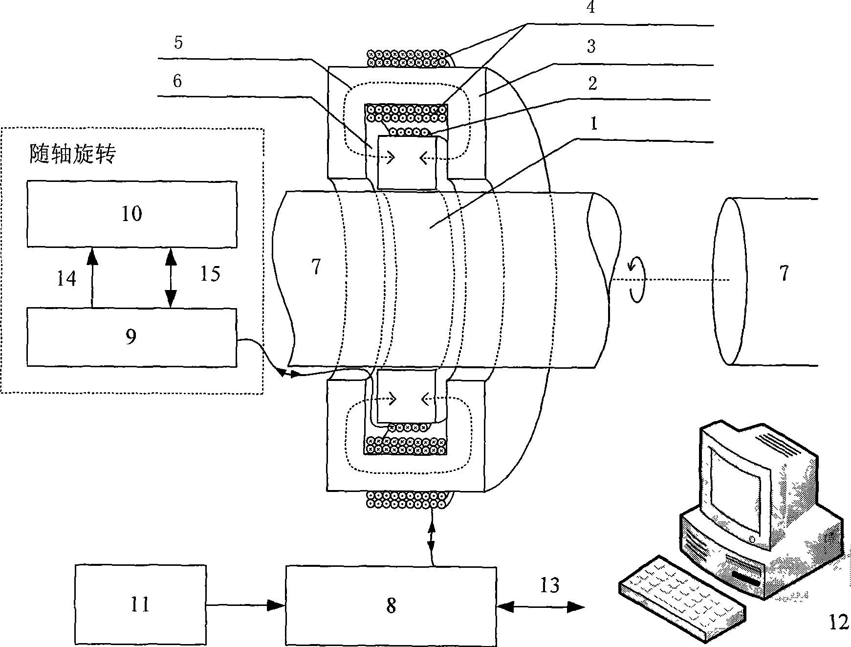
[0043] Embodiment 2 provides an electric energy and signal transmission structure of a coaxial rotary moving part with an air gap. It is applied to the non-contact power supply and communication of the temperature measuring device on the flywheel of an electromechanical equipment.

[0044] like figure 2As shown, the difference between Embodiment 2 and Embodiment 1 is that the rotating high-frequency ferrite 1 is sleeved and fixed on the rotating shaft 7 , and the coil 2 is wound on the outer layer of the magnetic ring-shaped rotating high-frequency ferrite 1 . There is a fixed coil 4 inside the magnetic ring formed by the fixed high-frequency ferrite 3; There is an air gap 6 between the rotating high-frequency ferrite 1 and the coil 2 and the fixed high-frequency ferrite 3 and the fixed coil.

[0045] Likewise, the stationary coil 4 is connected to the stationary part of the circuit 8; the rotating coil 2 is connected to the rotating part of the circuit 9 which rotates with...


PUM


Abstract

The invention relates to a technology for rotating or moving mechanical part non-contact type power supply and information transmission, in particular to a non-contact type electric energy and data integral slip ring type transmission method. The method is characterized in that two oppositely movable permeability magnetic materials are at least included, induction coils are respectively arranged in the two oppositely movable permeability magnetic materials, and an air gap is formed between the two oppositely movable permeability magnetic materials; one induction coil of the two oppositely movable induction coils converts the electric energy into energy of electromagnetic field, and the energy of electromagnetic field is transmitted to the other coil by using the loosely-coupled electromagnet induction transmission principle. The non-contact type electric energy and data integral slip ring type transmission method has high reliability and long service life, and not only can transmit the high-power electric energy in a non-contact type, and realizes the bidirectional multichannel data communication at the same time.

Description

technical field [0001] The invention belongs to the field of mechatronics. It relates to a technology for non-contact power supply and information transmission for rotating or moving mechanical parts, or a non-contact electric energy and data integrated slip ring transmission method. Background technique [0002] Various radars, rate turntables, gyroscopes, inertial platforms used in aerospace, aviation, navigation, and satellites, as well as automated electronic devices, such as machine joints, rotating arms, and other electronic equipment, often use sliding electrical contacts that match conductive rings and brushes. Device (also known as: bus ring, conductive slip ring, collector ring) for power and signal transmission. [0003] Modern electronic equipment, especially military equipment, requires such electrical contact devices to have high reliability and long service life. The traditional electrical contact device uses the method of dynamic contact between the brush a...

Claims


Application Information

Patent Timeline
IPC IPC(8): H02J17/00H02J50/10H04B5/00
Inventor 李小平谢楷刘彦明王海白丽娜
Owner XIDIAN UNIV
Learn More