
Filling knitting machine

A technology of flat knitting machine and triangular carriage, which is used in textiles and papermaking, instruments, weft knitting, etc., can solve the problem of high machine body, and achieve the effects of improving weaving speed, reducing rigidity and easy setting.

Active Publication Date: 2009-07-08
SHIMA SEIKI MFG LTD
View PDF0 Cites 8 Cited by
  • Summary
  • Abstract
  • Description
  • Claims
  • Application Information

AI Technical Summary

Problems solved by technology

The speed increase of the flat knitting machine needs to increase the speed of the carriage, but with the travel of the carriage, a large vibration will be generated on the flat knitting machine, which will cause noise. Due to the vibration, the machine body needs high rigidity.

Method used


Image

  • Filling knitting machine
  • Filling knitting machine
  • Filling knitting machine

Examples


Embodiment

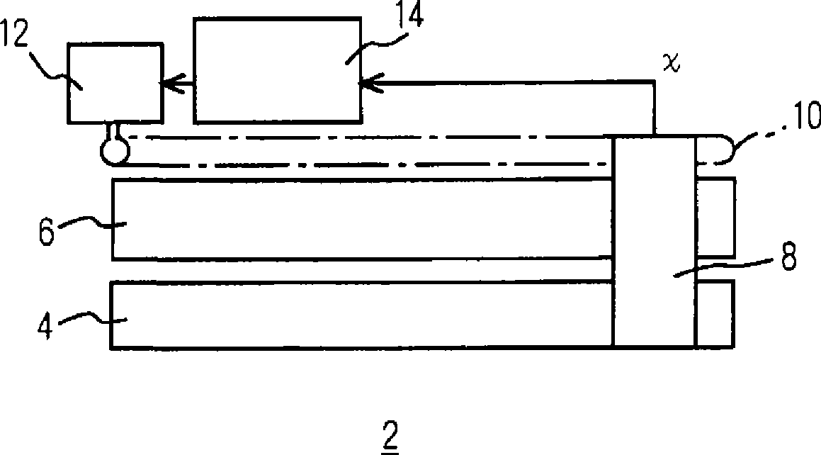
[0033] Figure 1 to Figure 5 The flat knitting machine 2 of the embodiment and its operation are shown. In each figure, 4 is a needle bed on the front side, 6 is a needle bed on the rear side, each may be one, or each may be two or each three, 8 is a carriage, and 8 is a carriage. The needle beds 4 , 6 are reciprocated, for example, by an endless belt 10 . 10 is a toothed belt, but it may also be a chain, and a pair may be provided at the front and back of the needle bed 4 . Furthermore, the carriage may be moved by a linear motor or the like. 12 is a travel motor, which drives the belt 10 to make the carriage 8 travel. 14 is the control part of the flat knitting machine 2.

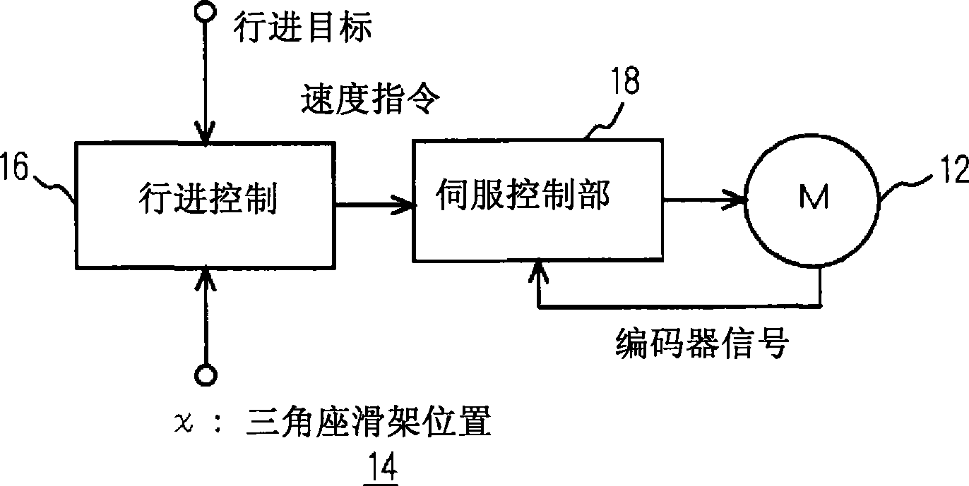
[0034] Such as figure 2 As shown, the travel control unit 16 inputs a travel target such as the position of a turning point from a not-shown upper-level control unit, and inputs a position x of the carriage 8 from a not-shown sensor. The travel control unit 16 generates a speed command based on the...


PUM


Abstract

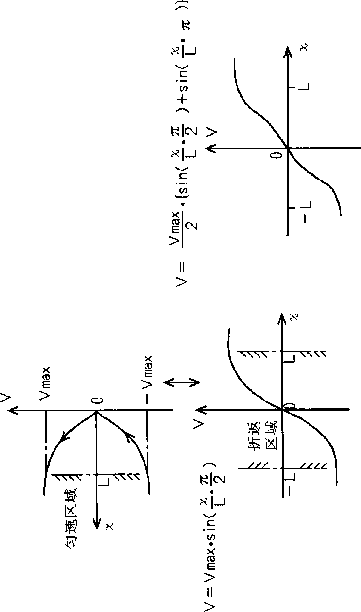
A flat knitting machine in which the speed of a carriage is set such that the acceleration thereof is maximized in the vicinity of a return point and the speed and the acceleration are smoothly changed between a fixed speed area and the return point. Accordingly, the vibration of the flat knitting machine can be reduced.

Description

technical field [0001] The invention relates to a knitting machine in which a carriage on a needle bed reciprocates on a flat knitting machine, a glove knitting machine, a sock knitting machine and the like. Background technique [0002] A knitting machine in which a carriage reciprocates on a needle bed has been known for a long time. In this specification, such a knitting machine is referred to as a flat knitting machine. The speed increase of the flat knitting machine needs to increase the speed of the carriage, but the travel of the carriage will cause a large vibration on the flat knitting machine, and noise will be generated along with it. Due to the vibration, the machine body needs high rigidity. In order to suppress the vibration during running, the commonly used method in mechanical engineering is S-shaped control, which starts with a small acceleration from speed 0, and maximizes the acceleration between the highest speed and the position of speed 0. However, th...

Claims


Application Information

Patent Timeline
Patent Type & Authority Applications(China)
IPC IPC(8): D04B15/99D04B15/96
CPCG05B2219/43032G05B2219/43034G05B2219/43033D04B15/99D04B15/96G05B19/416G05B2219/45194D04B15/00D04B15/30
Inventor 南方胜次森淳
Owner SHIMA SEIKI MFG LTD
Learn More