
Joint and/or bearing arrangement

A bearing device and joint technology, applied in the directions of shafts and bearings, bearing components, pivots, etc., can solve the problems of difficult installation of the joint device, and achieve the effect of tight and well sealed connection

Inactive Publication Date: 2009-07-08
ZF FRIEDRICHSHAFEN AG
View PDF1 Cites 4 Cited by
  • Summary
  • Abstract
  • Description
  • Claims
  • Application Information

AI Technical Summary

Problems solved by technology

However, since the sealing sleeve is formed of a soft material with a low melting point, the installation of such a joint device becomes difficult. For this joint device, the joint bushing is directly embedded, for example compression molded, to have a particularly Still liquid and very hot, such as in a casing of metallic material

Method used


Image

  • Joint and/or bearing arrangement
  • Joint and/or bearing arrangement

Examples


Embodiment Construction

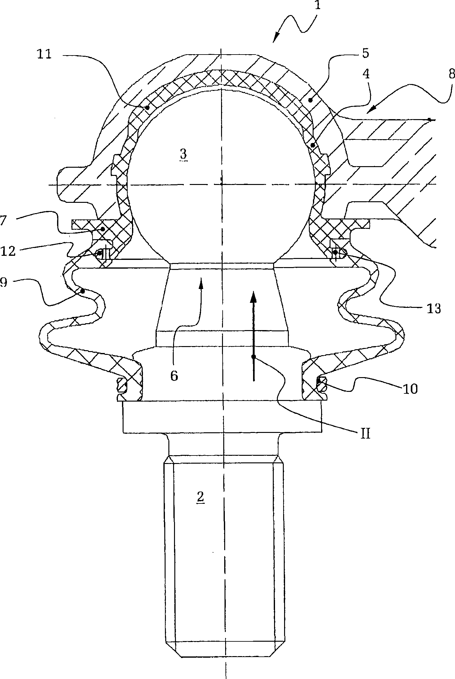
[0020] figure 1 The joint device 1 shown in FIG. 2 comprises an axially extending joint pin 2 with a widened top 3 formed, for example, by a substantially spherical profile. The top 3 can be held movably within or relative to a substantially continuously lubricated joint or bearing bush 4 , which is itself surrounded at least partially radially outwardly by a housing 5 .

[0021] For assembly, the joint tip 3 is first inserted into the joint bushing. The housing 5 is formed, for example, as an compression-molded part 8 or injection-molded part of the joint bush 4 with the joint tip 3 held therein. Liquid hot materials can be used for such compression molding or injection molding, which are formed from metal, for example as zinc die-casting parts, and are morphologically hard and dimensionally stable after subsequent cooling without further processing The housing 5 can then be formed integrally with, for example, an axle or a steering mechanism.

[0022] The joint and / or bea...


PUM


Abstract

The invention relates to a joint and / or bearing arrangement (1) which comprises a joint pin (2), the head section (3) of which is movable in relation to a receiving joint cup (4), and sealing collar (9) which is adjacent to a through opening (6) for the pin, said opening being provided in the region of a housing (5) which receives the joint cup (4), and said sealing collar being formed with the joint cup (4) to produce a common, single-piece unit. According to the invention, the joint cup (4) is surrounded by a metal housing (5) and, in the region of the through opening (6), comprises a deflector (7) having a radially outward-pointing component for shielding the sealing collar (9) from the housing (5).

Description

technical field [0001] The invention relates to a joint and / or bearing arrangement according to the preamble of claim 1 and to a joint and / or bearing arrangement having one or more such joints and / or bearing arrangements, especially in a chassis and / or steering gear Car. Background technique [0002] It is difficult for such joints to have pins which are held displaceably in joint bushes with their tops, wherein the joint bushes themselves are accommodated in the housing and are protected there against being pulled out. To allow the inside of the housing to obtain the necessary sealing with the contact surfaces on the one hand between the housing and the joint bushing and on the other hand between the joint bushing and the top in order to provide protection against contamination and to prevent lubricant from escaping. [0003] In order to fasten the sealing sleeve to the housing, it is known to provide a snap ring which surrounds the sealing sleeve from the outside and pres...

Claims


Application Information

Patent Timeline
Patent Type & Authority Applications(China)
IPC IPC(8): F16C11/06
CPCF16C11/0638F16C11/0671Y10T403/32704F16C11/06F16C33/72F16C33/06
Inventor F·布德
Owner ZF FRIEDRICHSHAFEN AG
Learn More