
Inflatable bag body

A technology of inflatable bags and gas passages, applied in the direction of preventing mechanical damage, packaging of vulnerable items, containers, etc., can solve the problems of buffer air bag damage, check valve damage, damage, etc., and achieve the effect of enhancing strength

Active Publication Date: 2009-07-15
KUNSHAN AIRBAG PACKING CORP
View PDF0 Cites 13 Cited by
  • Summary
  • Abstract
  • Description
  • Claims
  • Application Information

AI Technical Summary

Problems solved by technology

[0003] However, in order to provide a better cushioning protection effect, this kind of cushioning airbag is quite bulky, so it takes a lot of time to inflate, which is quite time-consuming and laborious. If the cushioning airbag is filled with high-pressure gas, it is easy to cause the cushioning airbag to collapse The check valve is damaged and cannot hold the air (in order to make the second diaphragm of the check valve produce air-holding action after inflation, the second diaphragm should be made very thin), or the outer membrane of the buffer air bag is damaged and deflated
In addition, this kind of buffer air bag is often damaged by scratches on the sharp corners or sharp corners of the items in the container, causing the gas in the buffer air bag to leak out and lose the function of buffer protection, and it must be discovered when the items are removed from the container. At this time, the item has been scratched or damaged due to the lack of a buffered intermediate medium during the transportation process.
[0004] It can be seen from this that how to improve the structure of the buffer air bag to solve the problem that the buffer air bag is easily damaged by the sharp corners and sharp corners of the items in the container, causing gas leakage and losing the function of buffer protection, and then by improving the buffer air bag and The structure of its check valve, to increase the inflation speed and reduce the time required for the inflation of the buffer air bag, is a problem that those skilled in the art are eager to solve

Method used


Image

  • Inflatable bag body
  • Inflatable bag body
  • Inflatable bag body

Examples


no. 1 example

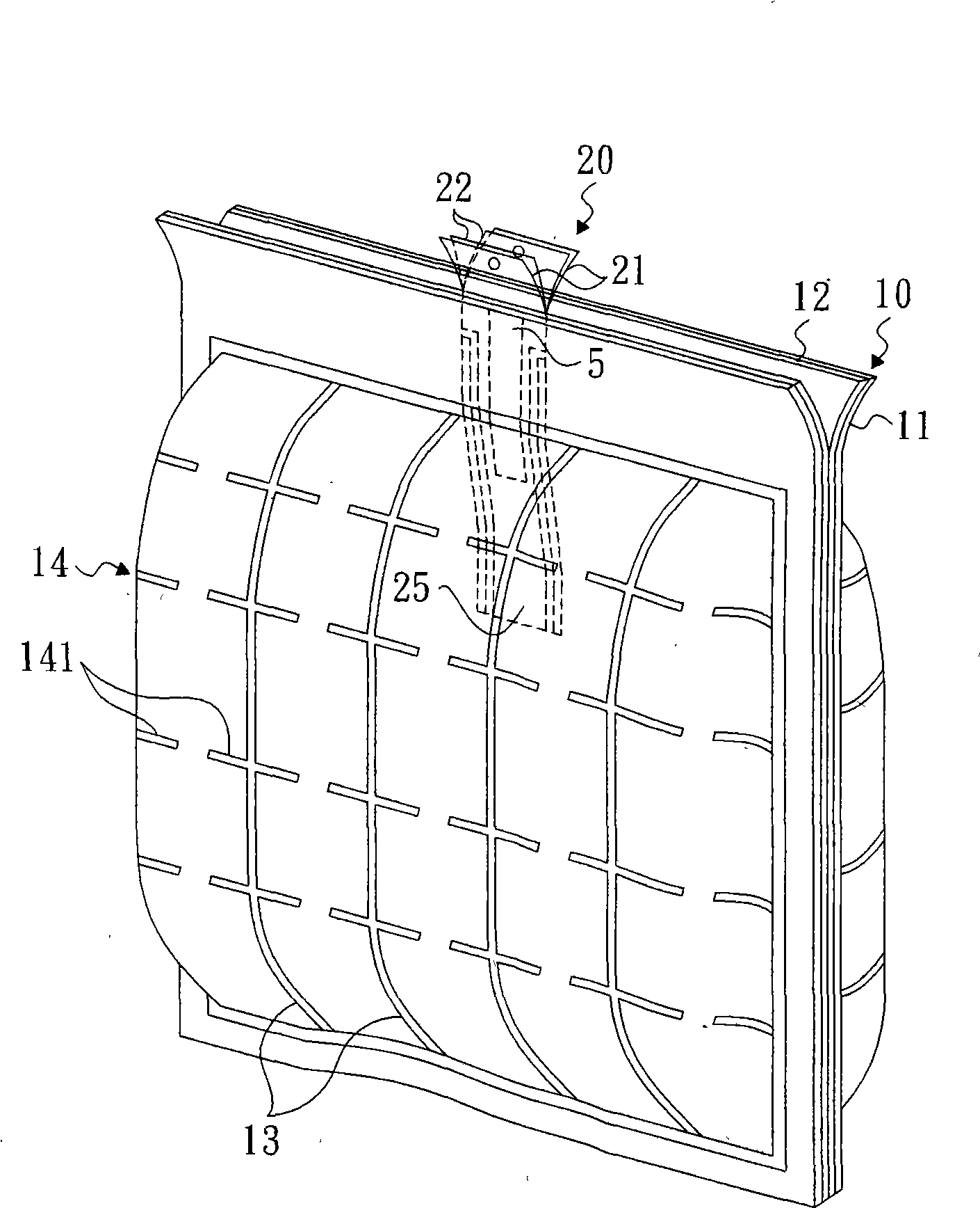
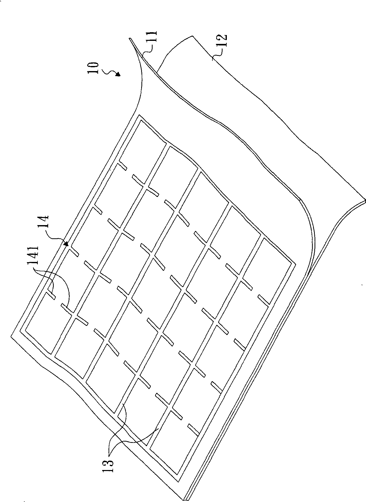
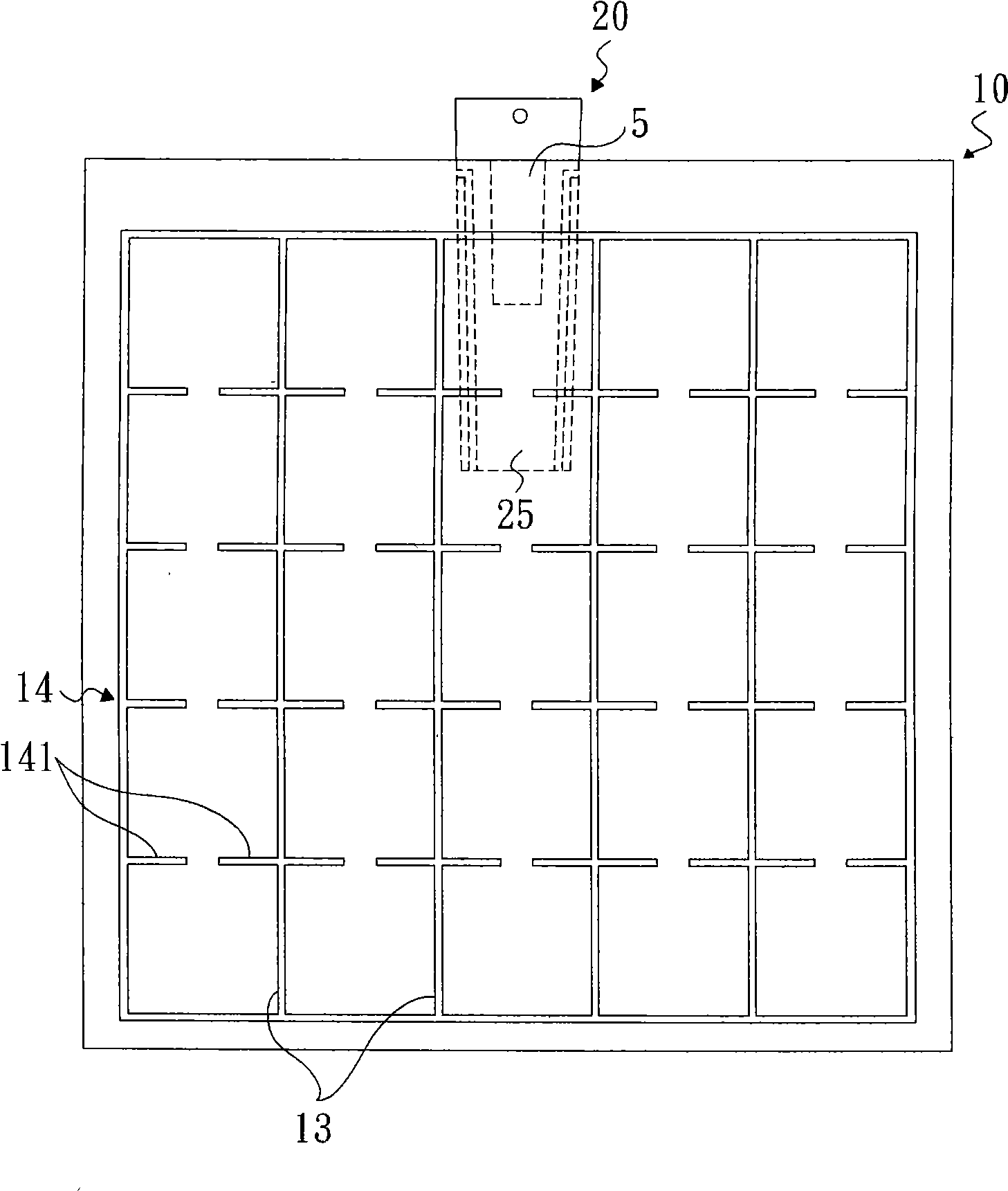
[0029] figure 1 , figure 2 , Figure 3A and Figure 3B Shown is the inflatable bag body of the first embodiment of the present invention, which includes: two outer membranes 10 stacked up and down, an air chamber 30 and a main air stop valve 20 .

[0030] The air chamber 30 is formed between the two outer films 10 by heat-sealing the sides of the outer film 10 , and the number of the air chambers 30 can be changed according to different structures and requirements. Each outer film 10 includes a first diaphragm 11 and a second diaphragm 12 stacked up and down, the first and second diaphragms 11, 12 can be made of the same material, for example polyethylene (polyethylene, PE), It can also be made of different materials, for example, polyethylene is used to make one of the first membrane or the second membrane, while the other is made of kraft paper. And there is no glue coated between the first diaphragm 11 and the second diaphragm 12, so they will not be glued together. T...

no. 2 example

[0035] Figure 4 Shown is a second embodiment of the invention. Different from the first embodiment, the main air stop valve 20 of this embodiment only includes two first inner films 21 stacked up and down, and the first heat-resistant material 5 is coated between the two first inner films. For example: printing heat-resistant glue or ink in printing. The first air inlet 24 and the first gas channel 25 are formed between the two first inner films 21 by heat sealing, so that the air chamber 30 communicates with the outside world.

no. 3 example

[0037] Figure 5 , Image 6 , Figure 7 Shown is the third embodiment of the air bag body of the present invention.

[0038] In this embodiment, multiple first heat-sealing lines 13 separate the first membrane 11 and the second membrane 12 into multiple air columns 16, and multiple second heat-sealing lines 14 separate each air column 16 It is divided into a plurality of air column sections 161 , and each air column section 161 on each air column 16 communicates with each other.

[0039]An inflation passage 17 and a plurality of auxiliary air stop valves 18 are also arranged between the first diaphragm 11 and the second diaphragm 12. It is formed by connecting the first diaphragm 11 and the second diaphragm 12. The auxiliary air stop valve 18 includes two auxiliary inner membranes 180 stacked up and down, on which a heat sealing point 18c is formed by means of heat sealing, and the heat sealing point makes the first diaphragm 11 and a piece of auxiliary inner membrane 180 ...


PUM


Abstract

The invention provides an inflating bag body which comprises two outer films, wherein the two outer films are bound in a heat sealing and bonding mode to form an air chamber and a main check valve, each outer film comprises a first film piece and a second film piece, the main check valve is positioned in an air chamber arranged between the two outer films, the upper end of the main check valve is higher than the upper ends of the two outer films, and the main check valve comprises a first air channel which is used for communicating the air chamber with the outside. When outside air enters the air chamber along the first air channel and leads the air chamber to expand, the air pressure in the air chamber can oppress the main check valve to seal the first air channel. The strength of the outer films is greatly strengthened by the structure; when one of the first film piece and the second film piece is damaged, air in the air chamber can not leak outside and can still constantly and effectively supply buffering and protecting function to an article; the structure of the main check valve can ensure that when high-pressure air is inflated into the air chamber, the main check valve can not be damaged because of the high pressure, and the inflating bag body not only can be quickly inflated, but also has better air sealing effect.

Description

technical field [0001] The invention relates to an inflatable bag body, in particular to an inflatable bag body with reinforced outer membrane structure. Background technique [0002] Generally, when large-scale items are transported in containers, buffer air bags are placed between the items to cushion and protect the items, reduce scratches or damage caused by collisions during transport, and improve the yield rate during transport. [0003] However, in order to provide a better cushioning protection effect, this kind of cushioning airbag is quite bulky, so it takes a lot of time to inflate, which is quite time-consuming and laborious. If the cushioning airbag is filled with high-pressure gas, it is easy to cause the cushioning airbag to collapse The check valve is damaged and cannot hold the air (in order to make the second diaphragm of the check valve produce air-holding action after inflation, the second diaphragm should be made very thin), or the outer membrane of the ...

Claims


Application Information

Patent Timeline
Patent Type & Authority Applications(China)
IPC IPC(8): B65D81/03B65D85/30
Inventor 廖建华廖耀鑫廖耀全
Owner KUNSHAN AIRBAG PACKING CORP
Learn More