Check patentability & draft patents in minutes with Patsnap Eureka AI!

Control method of basic input/output system

A technology of basic input and output and control method, applied in the direction of program control device, multi-programming device, program loading/starting, etc., can solve the problem that the basic interface and application method do not change much.

Inactive Publication Date: 2009-07-15
ASUSTEK COMPUTER INC
View PDF0 Cites 2 Cited by
  • Summary
  • Abstract
  • Description
  • Claims
  • Application Information

AI Technical Summary

Problems solved by technology

Although the functions of the BIOS program have increased, its basic interface and application methods have not changed much.

Method used


Image

  • Control method of basic input/output system
  • Control method of basic input/output system
  • Control method of basic input/output system

Examples


Embodiment Construction

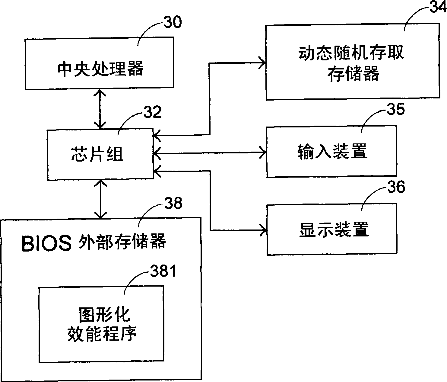
[0014] See image 3 , which is a functional block diagram of a preferred embodiment of the computer system proposed by the present invention. The computer system mainly includes: a central processing unit (CPU) 30, an input device (Input Device) 35, a display device (Display Device) 36, a dynamic random access memory (Dynamic Random Access Memory, hereinafter referred to as DRAM) 34 , a BIOS external memory 38 and a chipset 32 ​​(such as comprising a North Bridge chip and a South Bridge chip) that are signal-connected to the above-mentioned devices; wherein the BIOS external memory 38 internally stores a Basic Input Output System (BIOS) program and a compressed graphic Performance setting program 381 .

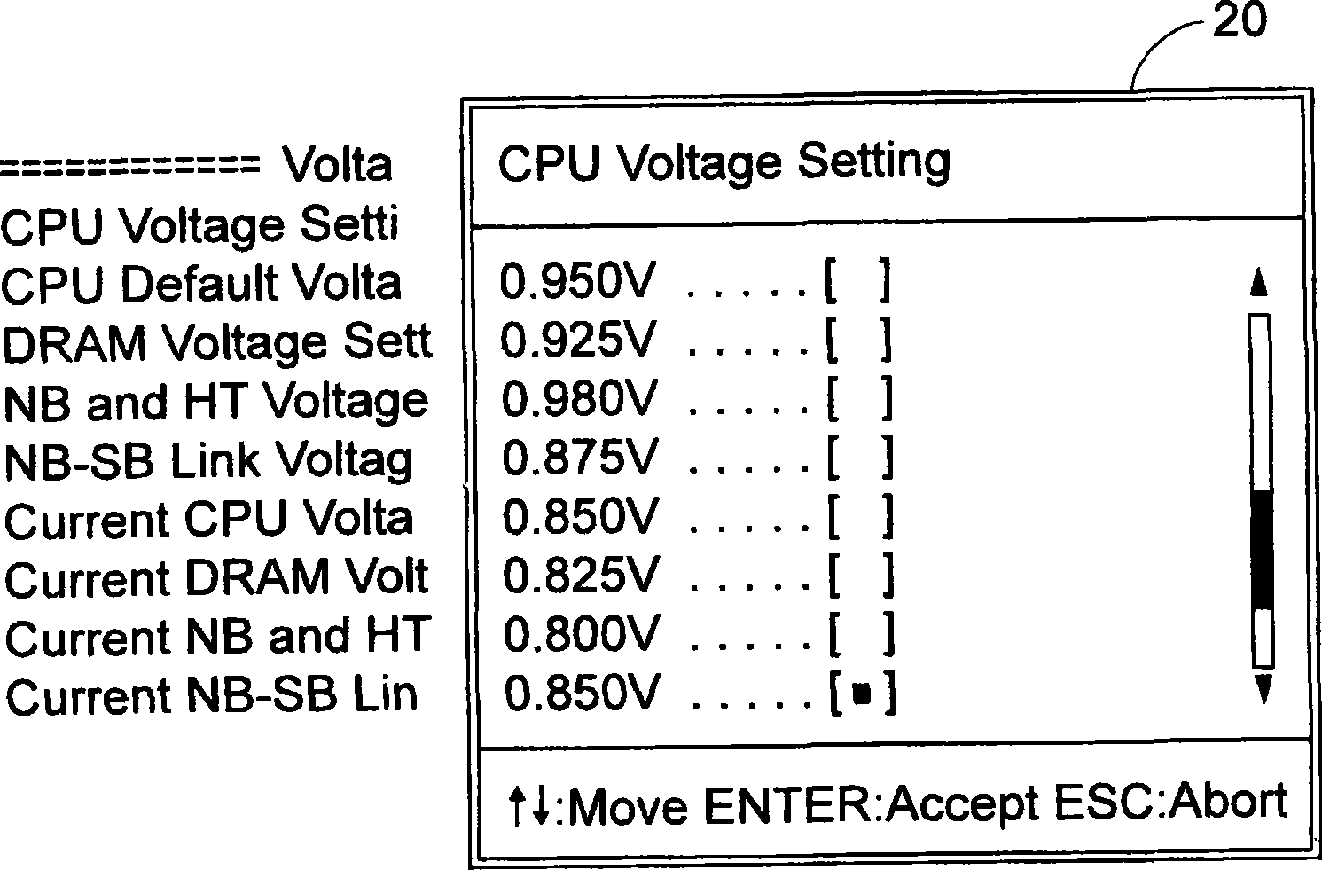
[0015] The method of the graphical overclocking user interface proposed by the present invention is to use the graphical performance program 381 to change the known overclocking user interface of the BIOS program.

[0016] Firstly, an application programming interface (Appli...


PUM


Abstract

A control method of basic input / output system is applied to a computer system, wherein the method comprises the following steps: in a computer opening process of computer system, because a user triggers an actuating graphic efficiency setting program event, executing a graphic efficiency setting program; obtaining the efficiency parameter of computer system and generating a halting function by the graphic efficiency setting program; correspondingly obtaining a halting service program by a video pattern card basic input-output system by the halting function for graphically outputting the efficiency parameter of computer system obtained by a graphic efficiency setting program to a display device, and furthermore generating a user overclocking interface.

Description

technical field [0001] This case is a control method of a basic input and output system, especially a control method for adjusting system parameters by using a graphical user interface in the basic input and output system. Background technique [0002] At present, when a computer system is turned on, a central processing unit (CPU) is used to execute a Basic Input / Output System (BIOS) program stored in an external memory to complete the booting action. The external memory is generally a non-volatile memory (Non-volatile memory), and the BIOS program is the most basic firmware program (firmware program) code on the motherboard hardware system. The main function is the self-test (power on) when the computer system is turned on. self-test, POST), initialization actions (initialize), recording computer system settings, and providing a resident program library. [0003] See figure 1 , which is a schematic functional block diagram of a known computer system. The computer system...

Claims


Application Information

Patent Timeline
IPC IPC(8): G06F9/445G06F9/46
Inventor 王锦煜
Owner ASUSTEK COMPUTER INC
Features
  • R&D
  • Intellectual Property
  • Life Sciences
  • Materials
  • Tech Scout
  • Unparalleled Data Quality
  • Higher Quality Content
  • 60% Fewer Hallucinations
Learn More