Switch capacitor band-pass filter and continuous time band-pass filter

A technology of band-pass filters and switched capacitors, applied to networks using time-varying elements, electrical components, impedance networks, etc., can solve problems such as the inability to achieve independent adjustment of ω

Inactive Publication Date: 2009-07-15
MIARTECH
View PDF0 Cites 5 Cited by
  • Summary
  • Abstract
  • Description
  • Claims
  • Application Information

AI Technical Summary

Problems solved by technology

But due to α 3 = K ω 0 ,

Method used


Image

  • Switch capacitor band-pass filter and continuous time band-pass filter
  • Switch capacitor band-pass filter and continuous time band-pass filter
  • Switch capacitor band-pass filter and continuous time band-pass filter

Examples


Embodiment Construction

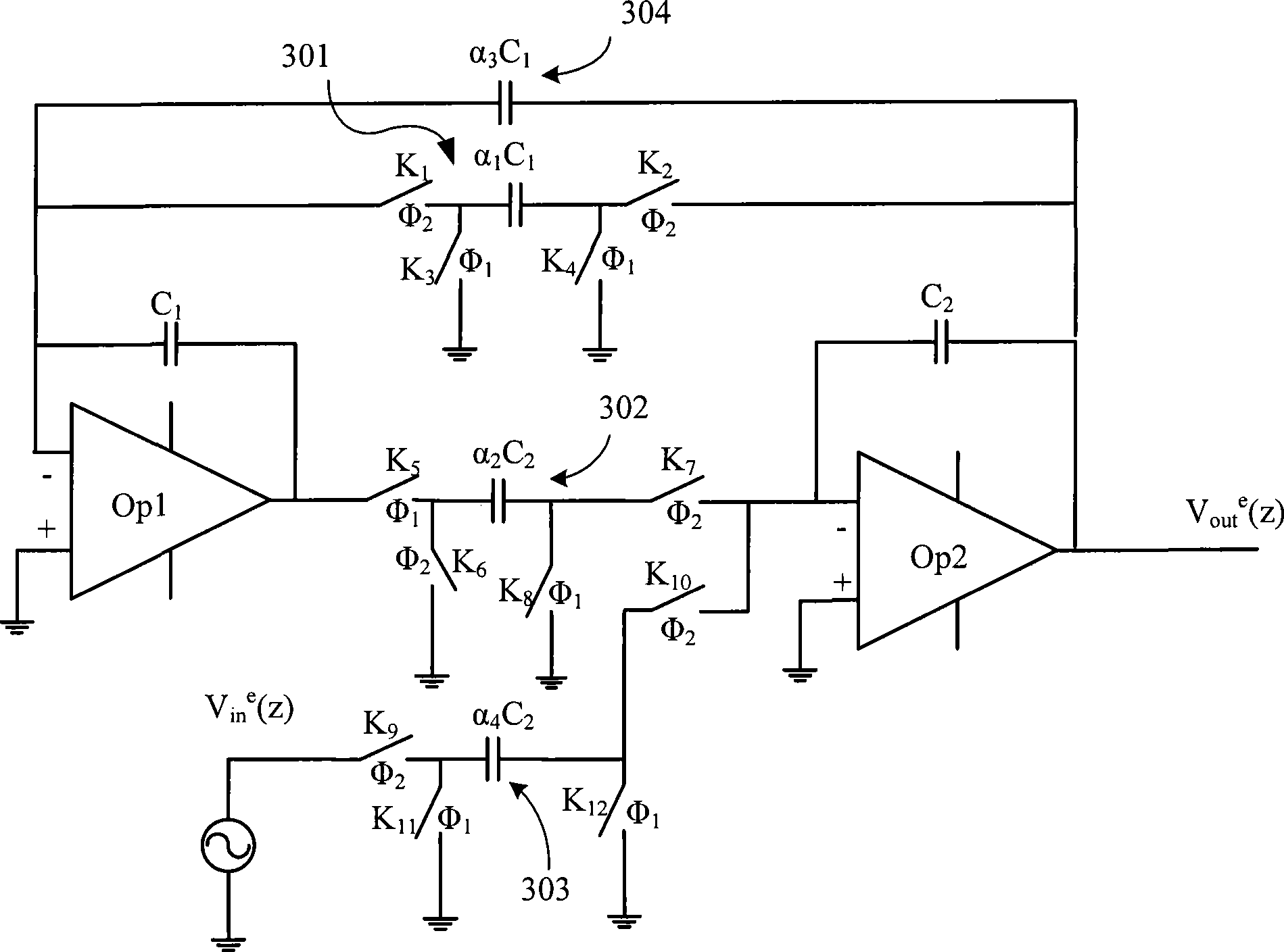
[0053] Embodiments of the present invention describe a method that can realize ω 0 , , K independent programming linear programming of the second-order filter.

[0054] Please refer to image 3 As shown, the second-order filter of an embodiment of the present invention is mainly composed of the following components: first and second operational amplifiers (hereinafter referred to as operational amplifiers) OP1, OP2, two integrating capacitors C1, C2, first to third switches Capacitors 301 - 303 and an adjustment capacitor 304 . Among them, C1 and C2 also represent the capacitance value of the integral capacitor. And the capacitance value of the capacitive element in the first switched capacitor 301 is α 1 C1, the capacitance value of the capacitive element in the second switched capacitor 302 is α 2 C2, the capacitance value of the capacitive element in the third switched capacitor 303 is α 4 C2, the capacitance value of the adjustment capacitor 304 is α 3 C1. here α ...


PUM


Abstract

The present invention relates to a switch capacitance second order band-pass filter which is provided with four programmable capacitors, if two integrating capacitor values of the filter are C1 and C2 respectively, capacitance values of four programmable capacitor are Alpha1C1, Alpha2C2, Alpha3C1, Alpha4C2, wherein, Alpha1-Alpha4 satisfies: Alpha1=Alpha2=Omega0T, Alpha3=1/Q, Alpha4=KT. Wherein, Omega0 is filter center frequency, Q as filter figure of merit, and K as filter gain coefficient. Thereby the three parameters can be adjusted independently. The present invention also puts forward continuous time RC structure with above band-pass filter and difference structure.

Description

technical field [0001] The invention relates to a filter circuit, in particular to a switched capacitor band-pass filter and a continuous time band-pass filter. Background technique [0002] Bandpass filter is a very widely used analog circuit. Cascading basic second-order bandpass filters is a common way to construct higher-order bandpass filters. In this cascade mode, finding a suitable second-order band-pass filter structure becomes the key to technology. [0003] In the application of filters, for various needs, it is often necessary to programmatically control the filtering characteristics of the filter. Sometimes it is to correct the deviation of frequency, Q value and gain characteristics due to process deviation or design mismatch (Mismatch), and sometimes it is because the filter itself needs to have controllable frequency characteristics (mainly refers to the passband frequency, in-band ripple, and gain). [0004] At this time, the value of some resistors or ca...

Claims


Application Information

Patent Timeline
IPC IPC(8): H03H19/00
Inventor 陈胜宋朝盛
Owner MIARTECH
Why Eureka
Try Eureka