Fusion system for video monitoring system and video meeting system

A technology of a video surveillance system and a video conferencing system, which is applied in the field of image processing, and can solve the problem of less expansion and expansion functions of video conferencing

Active Publication Date: 2012-11-21
天地阳光通信科技(北京)有限公司
View PDF0 Cites 0 Cited by
  • Summary
  • Abstract
  • Description
  • Claims
  • Application Information

AI Technical Summary

Problems solved by technology

However, the expansion and expansion functions of video conferencing are relatively few, and the replacement of the overall equipment is usually required.

Method used


Image

  • Fusion system for video monitoring system and video meeting system
  • Fusion system for video monitoring system and video meeting system
  • Fusion system for video monitoring system and video meeting system

Examples


example 1

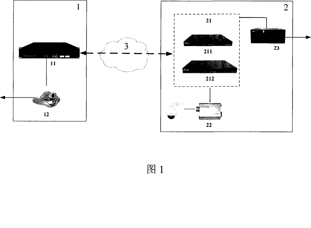
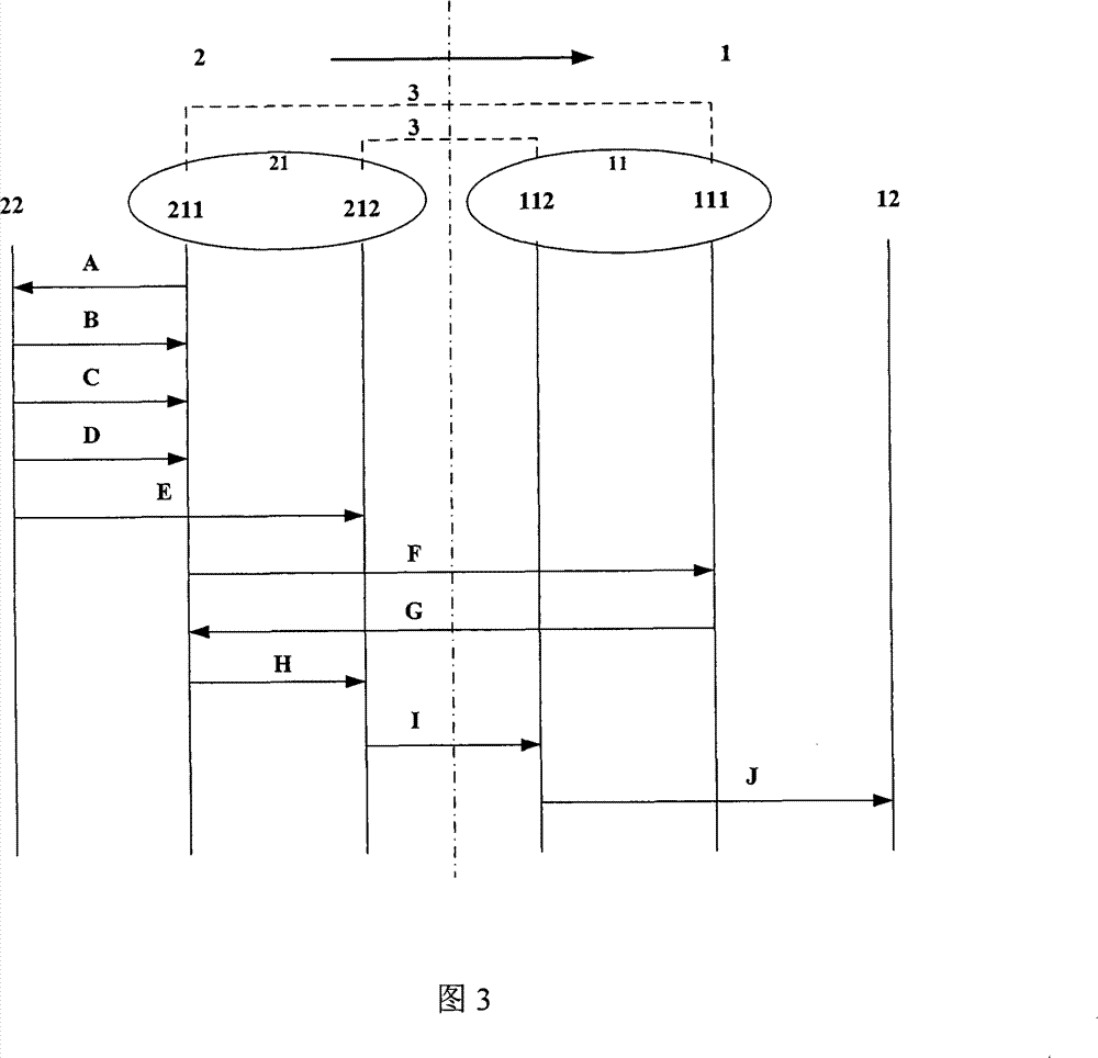
[0095] Example 1: if image 3As shown in the schematic diagram of the image display realization process from the video monitoring system 2 to the video conferencing system 1 in the present invention, image 3 The CCP includes: video conferencing system 1, video surveillance system 2 and IP network 3 that realizes the transmission and interaction of control data and media data streams, among which:

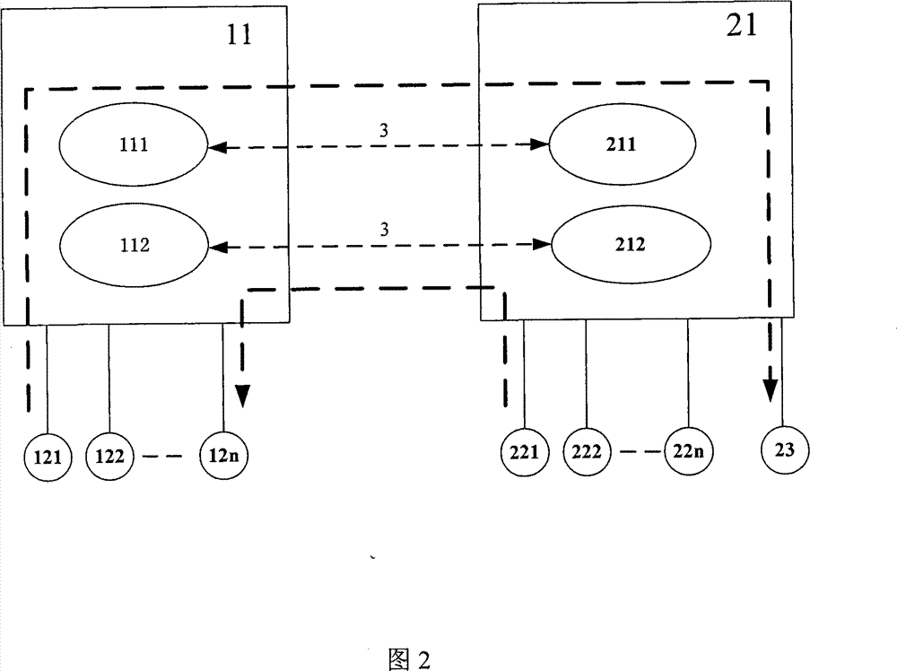
[0096] The video conferencing system 1 includes: a multipoint control unit 11 and a terminal 12 , wherein the multipoint control unit 11 includes: a multipoint controller 111 and a multipoint processor 112 .

[0097] The video monitoring system 2 includes: a video monitoring system control platform 21 and an encoder 22 of the video monitoring system 2, wherein the video monitoring system control platform 21 of the video monitoring system 2 includes an image scheduling control core unit 211 and an image transmission control core unit 212.

[0098] image 3 Between the multipoint c...

example 2

[0099] Example 2: if Figure 4 As shown in the schematic diagram of the image display realization process from the video conferencing system 1 to the video monitoring system 2 in the present invention, Figure 4 The CCP contains: video conferencing system 1, video monitoring system 2 and IP network 3 that realizes the transmission and interaction of both control data and media data streams, wherein: video conferencing system 1 includes: multi-point control unit 11 and terminal 12, wherein the multi-point Controller 111 contains: multipoint controller 111 and multipoint processor 112; video surveillance system 2 contains: video surveillance system control platform 21, encoder 22 and image decoding output control core unit 23, wherein video surveillance system control platform 21 contains An image scheduling control core unit 211 and an image transmission control core unit 212, wherein the image scheduling control core unit 211 has a built-in implementation of the H.323 protocol...


PUM


Abstract

An involvement system of a video monitor system and a video session system provided in the invention comprises that the video monitor system and the video session system are provided with an IP network for transmission, to thereby implement transmission and interaction of data through the IP network; a video monitor control platform of the video monitor system and a multipoint control unit of the video session system are both provided with separation processing of control data and media data, with one to one data processing structure, where a protocol processing module is set correspondingly in an image schedule control core unit of the video monitor system according to the protocol used by the video session system, to thereby implement display of the video monitor system coder, to the video session system terminal output to external televisions, and display from the video session system terminal to the video monitor system to the external large screen by means of the image decoder output control core unit. With the structure of P2P communication here provided, it implements communication of control data and media data, and resolves problems in current technology that the two sets of systems are independent to each other, without data commutation.

Description

technical field [0001] The invention belongs to the technical field of image processing, relates to the fields of a video monitoring system and a video conference system, and in particular relates to the intercommunication technology of the video monitoring system and the video conference system. Background technique [0002] Video conferencing is a typical interactive video application system. Its networking depends on professional video conferencing equipment (such as multi-point control unit, conference terminal, etc.), and the communication between devices requires strict protocol system (such as ITU-T H.323, etc.); while video surveillance focuses more on one-way video transmission, usually consisting of relatively simple video codecs, decoders, and control platforms. At present, there is no unified communication standard between devices. [0003] At present, for users who need to deploy two applications of video conferencing and video surveillance at the same time, it ...

Claims


Application Information

Patent Timeline
Patent Type & Authority Patents(China)
IPC IPC(8): H04N7/18H04N7/15H04L29/06
Inventor 汤敏蒋欣
Owner 天地阳光通信科技(北京)有限公司
Why Eureka
Try Eureka