Method and apparatus for encoding and decoding

A coding and code stream technology, which is applied in the field of image coding and decoding, can solve the problems of large dynamic range of disparity vector, inability to guarantee the effect, and inability to determine the disparity vector, etc., to achieve accurate estimation, improve the effect, and simplify the image coding process.

Inactive Publication Date: 2009-07-15
HUAWEI TECH CO LTD +1
View PDF0 Cites 34 Cited by
  • Summary
  • Abstract
  • Description
  • Claims
  • Application Information

AI Technical Summary

Problems solved by technology

[0005] However, in the process of realizing the present invention, the inventors found that since the motion vector is caused by the movement of the object and the camera, and the disparity vector is caused by the offset of the camera position, there are many differences between the disparity vector and the motion vector , making it impossible to determine the accurate disparity vector by using the method of determining the motion vector
[0006] First of all, if the camera used to obtain the image satisfies the parallel setting and correction, the disparity vector is a scalar, and the motion vector obtained by motion estimation is a two-dimensional vector; moreover, for the single-view motion sequence, the motion vector domain has time Domain correlation, while the predicted value of the disparity vector has nothing to do with the time domain; therefore, due to the difference between the motion vector and the disparity vector, if the disparity vector is determined by the motion vector, it will not be possible to obtain a satisfactory disparity vector value
[0007] Moreover, usually the dynamic range of the disparity vector is relatively large. Taking an image with a size of 640×480 pixels as an example, in a stereo pair, the horizontal displacement of 30-50 pixels may often appear, sometimes even up to 100 pixels, and the motion vector will not have such a large dynamic range; therefore, due to the relatively large dynamic range of the disparity vector, if the motion estimation method in the traditional single-view video coding is used, the search range needs to be set very large. Large, and there is no guarantee that great results will be obtained

Method used


Image

  • Method and apparatus for encoding and decoding
  • Method and apparatus for encoding and decoding
  • Method and apparatus for encoding and decoding

Examples


Embodiment Construction

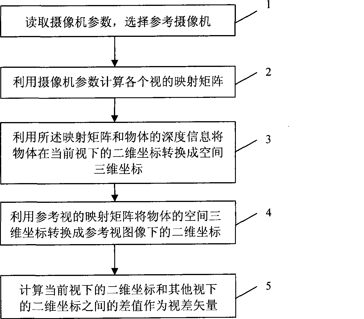
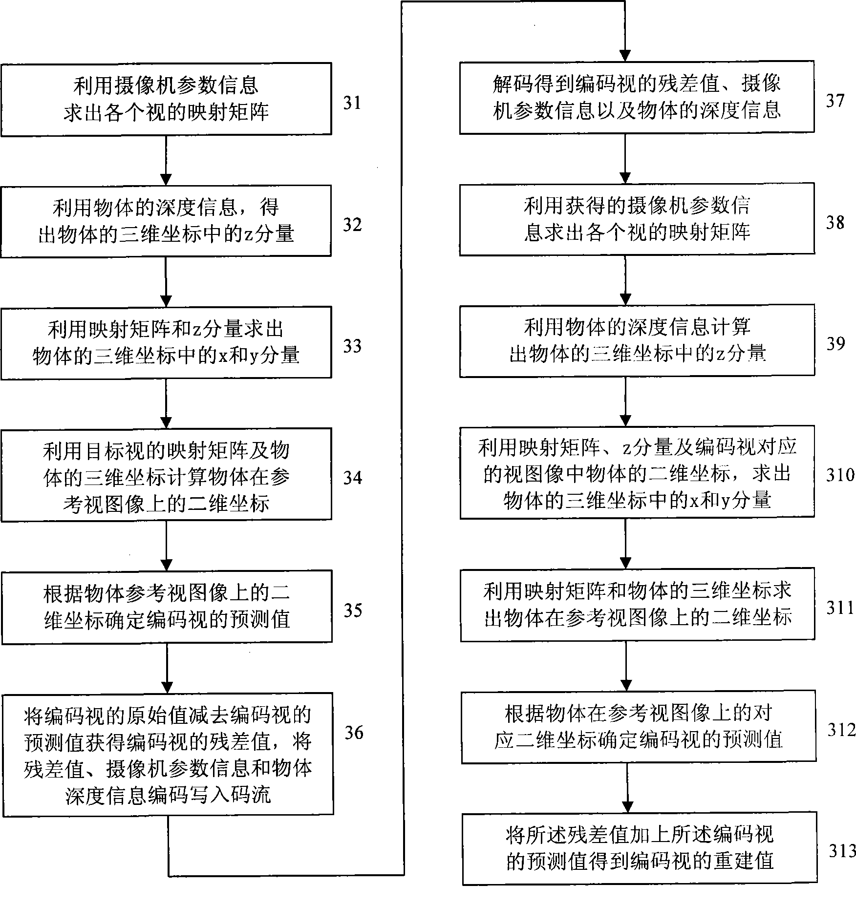
[0037] Embodiments of the present invention provide an implementation scheme for obtaining disparity vectors in the encoding process. Considering that the position of the camera is fixed, the disparity vector is mainly determined by the depth information of the object (the distance between the space object and the camera) and the camera parameters. Therefore, the implementation scheme of making full use of the depth information of the object and the parameters of each camera to determine the corresponding disparity vector is adopted to achieve the purpose of accurately calculating the disparity vector between each view, and then the calculated disparity vector can be used as a multi-view encoding process. better encoding parameters.

[0038] That is to say, in the embodiment of the present invention, after the depth information of the object in the multi-view image coding process is known, according to the depth information and the known camera parameter information of each cam...


PUM


Abstract

An encoding method and device, mainly composed of: firstly, calculating mapping matrixes corresponding to various views according to camera parameter information corresponding to cameras of various views, the mapping matrix is mapping converting coefficient between 2-dimensional coordinates and 3-dimensional coordinates of each point on image of each view; then obtaining 3-dimensional coordinates of object according to mapping matrix corresponding to current view, 2-dimensional coordinates of object of current view and object depth information, and determining 2-dimensional coordinates of object of other view according to this 3-dimensional coordinates and mapping matrix corresponding to other views; then, calculating relative parallax vector or residual difference, and using this parallax vector or residual difference to carry out encoding operation. Embodiment of this invention leads to higher precision on parallax evaluation among different view with less residual difference, in order to effectively enhance multi-view image encoding effect and simplify image encoding process.

Description

technical field [0001] The invention relates to the technical field of image coding and decoding. Background technique [0002] In the field of multi-view image coding technology, the industry has always hoped to effectively use the correlation between different-view images to encode images. For this reason, the concept of disparity is proposed, which refers to the displacement between two projection points of the same spatial point on different image planes. [0003] In order to obtain accurate disparity, a corresponding disparity estimation operation is required. The disparity estimation (Disparity estimation) is the process of finding the disparity vector of the pixel or block corresponding to the current frame in the reference frame under certain criteria. The disparity vector is the disparity value to be determined. [0004] At present, since the process of determining the disparity vector is similar to the motion estimation process of determining the motion vector in...

Claims


Application Information

Patent Timeline
Patent Type & Authority Applications(China)
IPC IPC(8): H04N7/26H04N13/00G06T7/00H04N19/597
Inventor 何芸朱刚杨平许晓中郑建铧郑萧桢史舒娟
Owner HUAWEI TECH CO LTD
Why Eureka
Try Eureka