
Cable trolley protector for construction elevator

A technology for construction elevators and protectors, which is applied to elevators, elevators in buildings, transportation and packaging, etc. It can solve problems such as messy wires, limited elevator lifting height, and damage to cable trolleys. The method is simple, reliable, and easy to install and use. , The effect of protecting the cable trolley

Inactive Publication Date: 2009-07-22
于海旺
View PDF0 Cites 6 Cited by
  • Summary
  • Abstract
  • Description
  • Claims
  • Application Information

AI Technical Summary

Problems solved by technology

This method has the following disadvantages: 1. The cable rises and falls irregularly, and it is prone to disordered lines; 2. When the lifting height exceeds a certain height (usually about 200 meters), the self-weight of the cable often exceeds its own tensile strength. Strength, which affects the service life and safety of the cable, which also limits the lifting height of the elevator; 3. With the lifting of the ladder cage, the cable droops and swings, which can easily cause the cable to be hung by building attachments or construction elevator accessories live, resulting in cable breakage and leakage
The building construction hoist with the above structure avoids the shortcomings of the traditional construction hoist, but it also brings new problems, that is, during the operation of the building construction hoist, the cable trolley is easily affected by the construction conditions, such as during construction The operation is stopped due to the influence of strong wind, weather factors, construction waste, etc. At this time, the ladder cage continues to run, causing accidents such as the cable being pulled or squeezed and the cable trolley damaged.

Method used


Image

  • Cable trolley protector for construction elevator
  • Cable trolley protector for construction elevator
  • Cable trolley protector for construction elevator

Examples


Embodiment Construction

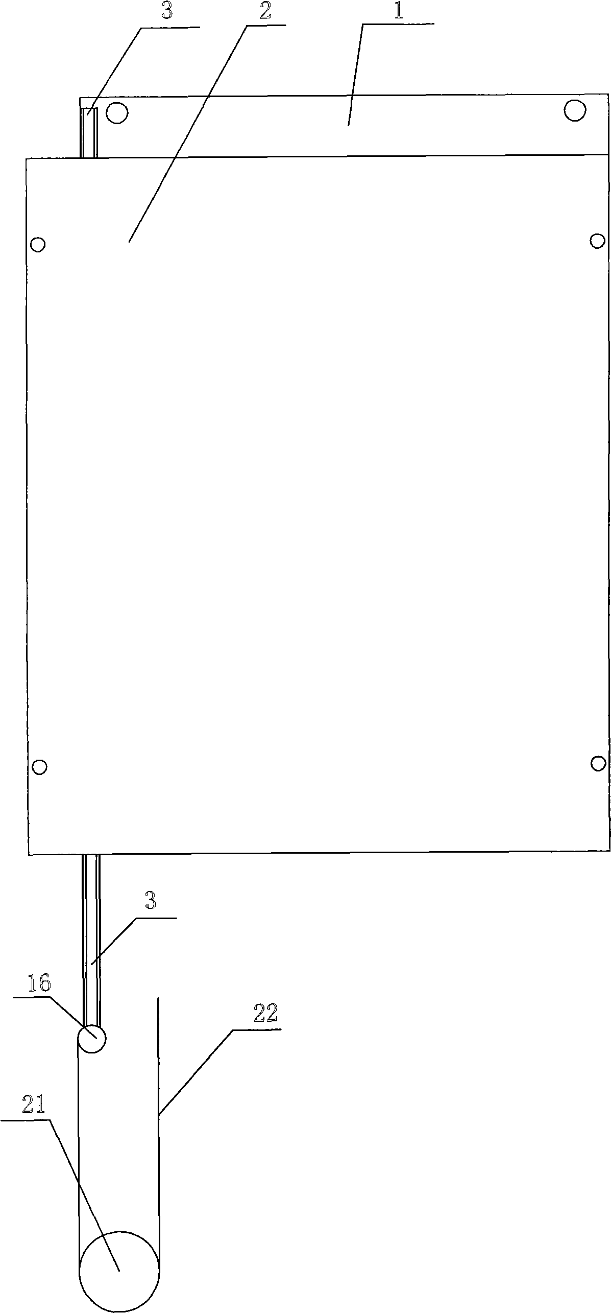
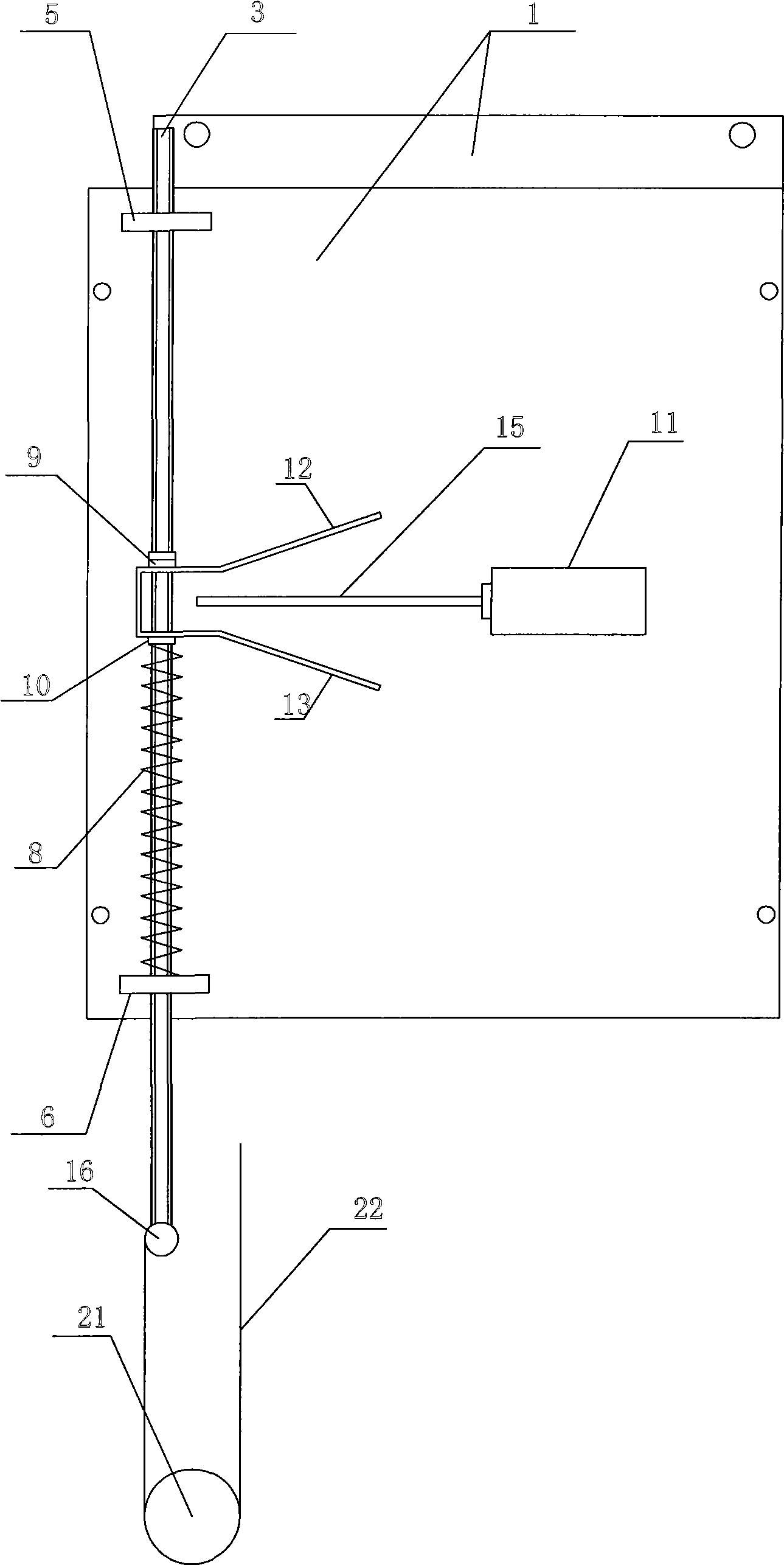
[0020] like figure 1 , figure 2 As shown, the construction hoist cable trolley protector of the present invention includes a housing, a limit switch 11 and a pull rod 3, the pull rod 3 is provided with threads, and the housing includes a bottom plate 1 and a cover plate 2 matched with the bottom plate 1, and the bottom plate 1 Also fixedly be provided with upper bearing 5 of pull rod and lower bearing 6 of pull rod, pull rod 3 wears on the upper and lower bearings 5,6 of the pull rod and is slidingly matched with the upper and lower bearings 5,6 of the pull rod. The middle part of the pull rod 3 is also provided with upper and lower adjustment nuts 9, 10, and the bottom of the pull rod 3 is also sleeved with a spring 8. The bottom end of the pull rod 3 is also provided with a pull ring 16, and the middle part of the pull rod 3 is also provided with upper and lower dials 12, 13 which are integrally arranged. Shape, the top of the upper dial 12 is press-fitted with the bottom...


PUM


Abstract

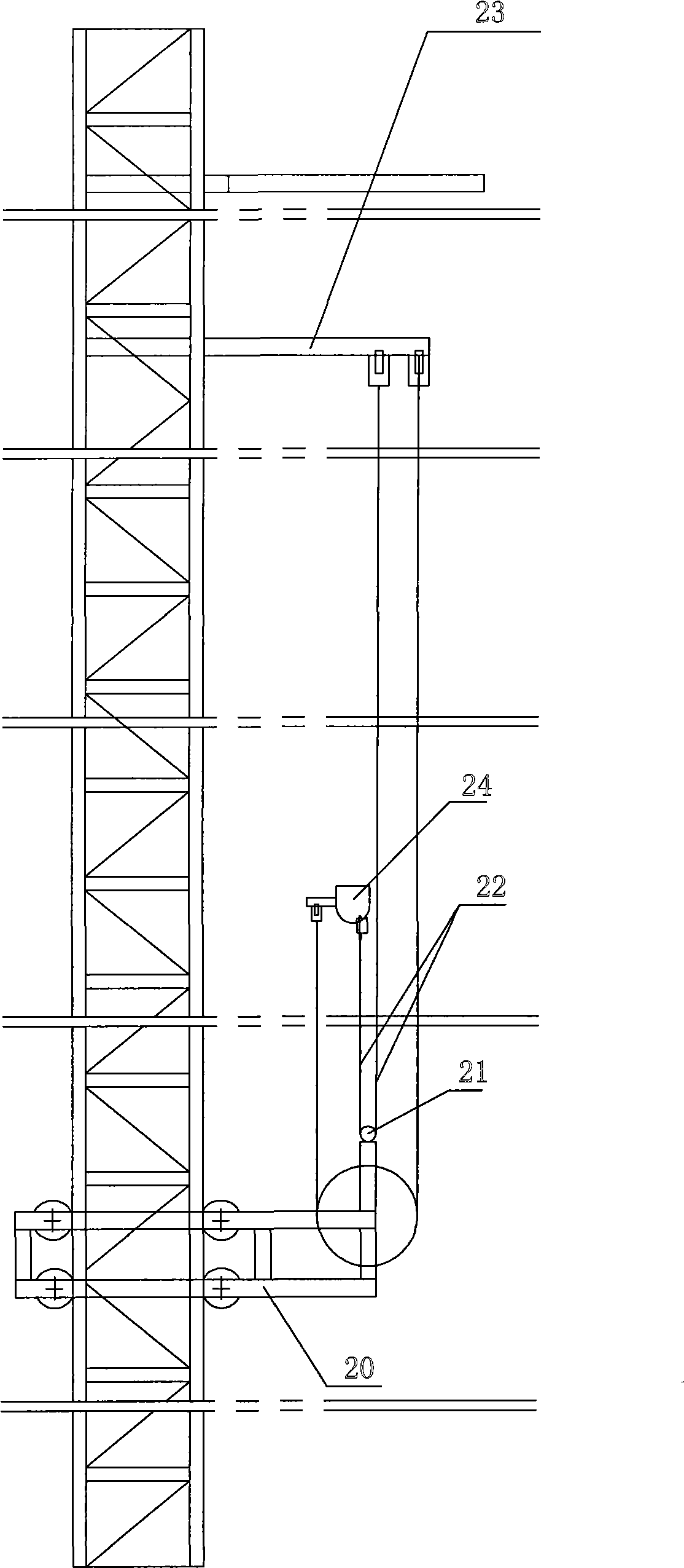
The invention discloses a cable trolley protector for construction hoists, comprising a shell with a motherboard, and a pull rod. An upper support and a lower support of the pull rod are fixedly arranged on the motherboard; the pull rod penetrates and is in sliding fit with the upper and the lower supports of the pull rod; a resetting device with the other end pressed on the pull rod is pressed on the lower support of the pull rod; and the pull rod is also in transmission connection with a trigger gear of a limit switch fixedly connected on the motherboard and controlled by and connected with a master control circuit of the hoist. When in use, the shell is arranged on a cable bracket of a cage and a pulley is arranged on a cable trolley; then a pull rope is fixedly connected at the lower end of the pull rod; the other end of the pull rope is moved around the pulley and then upwardly connected on a cable-picking holder of the hoist to adjust the tension of the pull rod so as to cause the trigger gear of the limit switch to be in non-trigger state. When the cable trolley is blocked during the operation, the tension of the pull rope is changed and the pull rod triggers the limit switch to stop the operation of the hoist, thus protecting the cables and the cable trolley.

Description

technical field [0001] The invention relates to a cable trolley protector for a construction hoist. Background technique [0002] When the traditional building construction elevator works, a cage for holding cables is placed under the elevator cage, and the cables are pulled up or dropped into the cage as the cage rises and falls. This method has the following disadvantages: 1. The cable rises and falls irregularly, and it is prone to disordered lines; 2. When the lifting height exceeds a certain height (usually about 200 meters), the self-weight of the cable often exceeds its own tensile strength. Strength, which affects the service life and safety of the cable, which also limits the lifting height of the elevator; 3. With the lifting of the ladder cage, the cable droops and swings, which can easily cause the cable to be hung by building attachments or construction elevator accessories live, resulting in the phenomenon of broken cable leakage. In order to solve the above ...

Claims


Application Information

Patent Timeline
Patent Type & Authority Applications(China)
IPC IPC(8): B66B5/02B66B7/06B66B9/16
Inventor 于海旺
Owner 于海旺
Learn More