Supercharge Your Innovation With Domain-Expert AI Agents!

Cast-in-situ concrete hollow slab

A technology of cast-in-place concrete and hollow slabs, which is applied in the field of cast-in-place concrete hollow slabs, and can solve the problems of time-consuming, high cost, and troublesome overall molding and production

Inactive Publication Date: 2009-07-22
湖南邱则有专利战略策划有限公司
View PDF3 Cites 3 Cited by
  • Summary
  • Abstract
  • Description
  • Claims
  • Application Information

AI Technical Summary

Problems solved by technology

However, when making this type of cavity mold shell, the overall molding is troublesome, labor-intensive and time-consuming, and the cost is high.

Method used


Image

  • Cast-in-situ concrete hollow slab
  • Cast-in-situ concrete hollow slab
  • Cast-in-situ concrete hollow slab

Examples


Embodiment Construction

[0149] The present invention will be further described below in conjunction with drawings and embodiments.

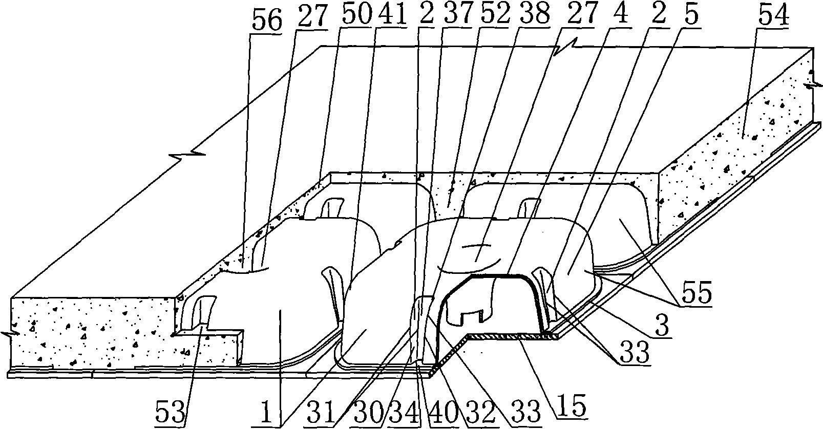
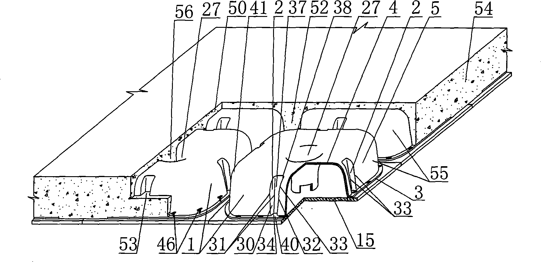
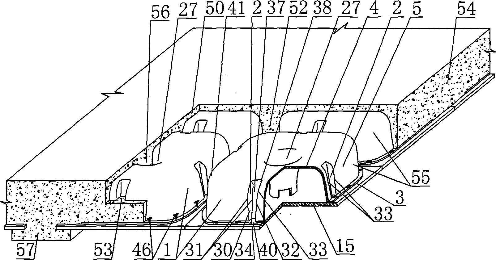
[0150] As shown in the accompanying drawings, the present invention is a cast-in-place concrete hollow slab, which includes cast-in-place concrete 54 and a mandrel 55. The mandrel 55 is wrapped in the cast-in-place concrete 54. 15, the pot-shaped member 1 is composed of a pot bottom plate 4 and a pot side wall 5, the pot side wall 5 is provided with a vertical groove 2, and the pot-shaped member 1 is also provided with a pick edge 3, and the core molds 55 are close to each other or alternately arranged, forming cast-in-place concrete ribs 52 between each other, and the cast-in-place concrete forms cast-in-place concrete bars 53 at the groove 2, which is characterized in that the basin-shaped component 1 is arranged on the prefabricated bottom plate 15, and the basin-shaped component 1 An orifice 27 is arranged in the middle, and the cast-in-place concrete forms a cast-i...


PUM


Abstract

A cast-in-place concrete hollow slab comprises a cast-in-place concrete (54) and core modules (55); the core modules (55) are wrapped in the cast-in-place concrete (54), the core modules (55) consist of a basin-shaped element (1) and a precast floor plate (15), and the basin-shaped element (1) consists of a basin floor plate (4) and a basin side wall (5), the basin side wall (5) is provided with a vertical groove (2), the basin-shaped element (1) is also provided with a raising edge (3), the core modules (55) are mutually and closely leaned against or alternately arranged, cast-in-place concrete ribs (52) are arranged between the core modules, and the cast-in-place concrete forms a cast-in-place concrete bar (53) at the groove (2) part. The hollow slab is characterized in that the basin-shaped element (1) is arranged on the precast floor plate (15), a hole tube (27) is arranged at the middle of the basin-shaped element (1) and a cast-in-place concrete frusta or pole (56) is formed on the hole tube (27) part of the cast-in-place concrete. The hollow slab is applicable to the cast-in-place reinforcing steel bar concrete or prestressed reinforcing steel bar concrete hollow floor cover, roof, wall, foundation slab and bridge, in particular to the use of the hollow floor cover.

Description

(1) Technical field [0001] The invention relates to a cast-in-place concrete hollow slab. (2) Background technology [0002] At present, the cast-in-place concrete hollow floor is a widely used floor structure, and the lightweight permanent tire mold filled in it includes hollow tubes and cavity formwork components. For example, the patent No. ZL99249798.1, which the applicant applied for on November 29, 1999, is a utility model patent named "fiber-reinforced thin-walled member for reinforced concrete filling", which discloses a thin-walled formwork member, including an upper plate, The surrounding side walls, the lower bottom, and the upper plate, the surrounding side walls and the lower bottom form a polyhedral cavity. Another example is that the application number applied by the applicant on November 23, 2001 is 01140106.0, the publication number is CN1356442, and the name is called "a kind of cavity structure formwork for cast-in-place reinforced concrete floor slab" pa...

Claims


Application Information

Patent Timeline
Patent Type & Authority Applications(China)
IPC IPC(8): E04B5/36E04C1/00E04C5/00E04B2/86E02D27/00E04G15/06E04G11/36
Inventor 邱则有
Owner 湖南邱则有专利战略策划有限公司
Features
  • R&D
  • Intellectual Property
  • Life Sciences
  • Materials
  • Tech Scout
  • Unparalleled Data Quality
  • Higher Quality Content
  • 60% Fewer Hallucinations
Learn More