
Double-ripple ventral shield steel case built-up beam

A technology of composite beams and double corrugations, which is applied to floors, structural elements, building components, etc., can solve the problems that traditional products are difficult to meet the requirements, it is difficult to realize automatic production, and increase the processing workload, so as to achieve beautiful welds without spatter , Excellent anti-fatigue performance, excellent light weight effect

Inactive Publication Date: 2008-07-16
TONGJI UNIV
View PDF1 Cites 38 Cited by
  • Summary
  • Abstract
  • Description
  • Claims
  • Application Information

AI Technical Summary

Problems solved by technology

This kind of component optimizes the performance of the component to a certain extent, especially the box-shaped section, which significantly improves the lateral deformation resistance and the overall torsional resistance of the component, but because it still uses flat steel plates as webs, so The amount of steel used for the web is still relatively large
[0006] my country's current steel structure code (GB50017-2003) has strict regulations on the web height-thickness ratio of welded H-shaped steel and welded steel box girders. When it exceeds a certain limit, certain methods such as welding stiffeners must be used to strengthen the web , which will increase the processing workload, and the welding process will also cause adverse effects such as stress concentration, and it is difficult to realize automatic production
Moreover, due to the limitation of processing technology and processing equipment, traditional hot-rolled I-beams and H-beams are difficult to achieve large-scale products. When the required load-bearing capacity and rigidity are large, traditional products are difficult to meet the requirements
If it is completed by designing, processing and welding H-shaped steel, it will be labor-intensive and time-consuming, increase the cost, and affect the construction speed

Method used


Image

  • Double-ripple ventral shield steel case built-up beam
  • Double-ripple ventral shield steel case built-up beam

Examples


Embodiment 1

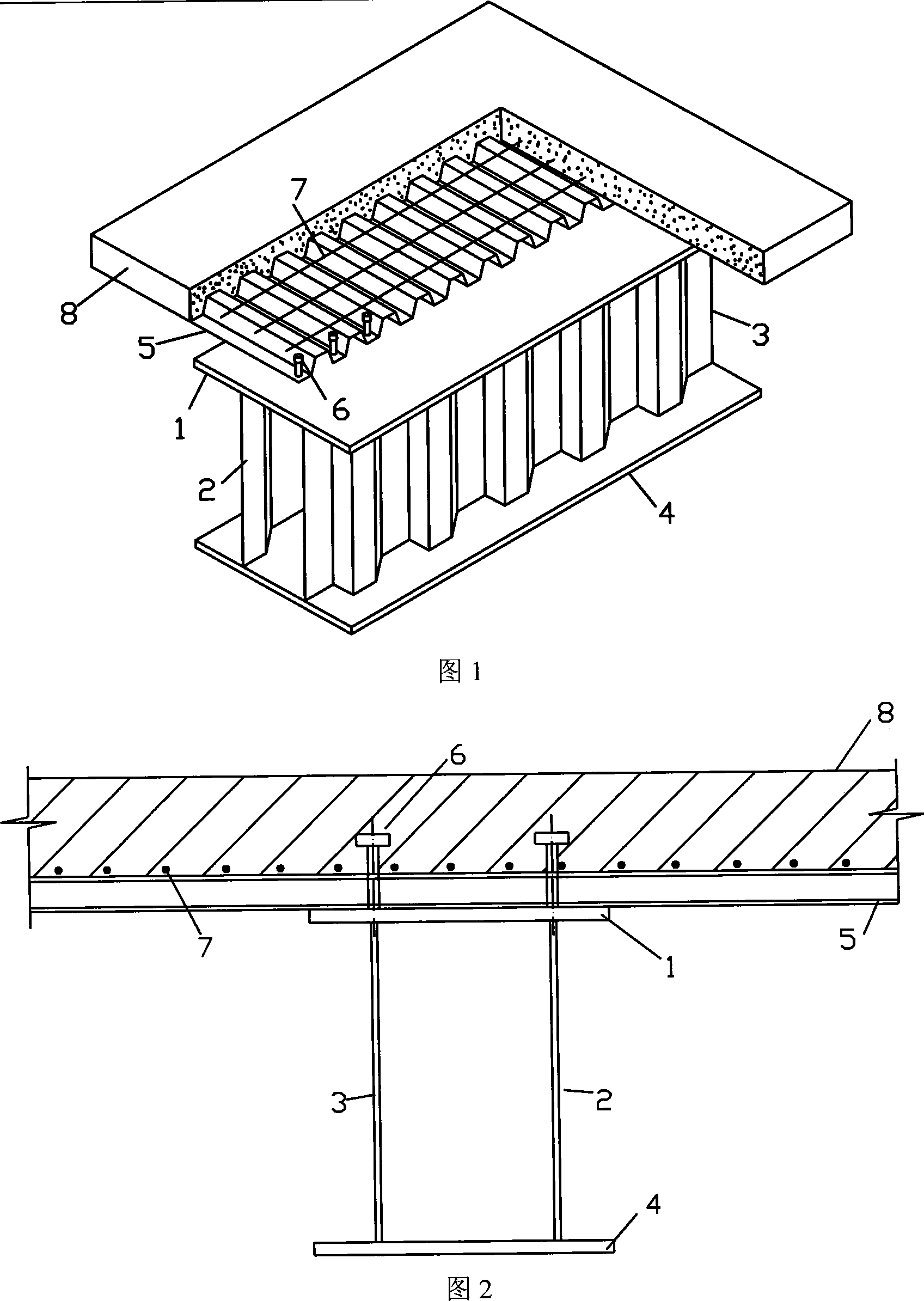
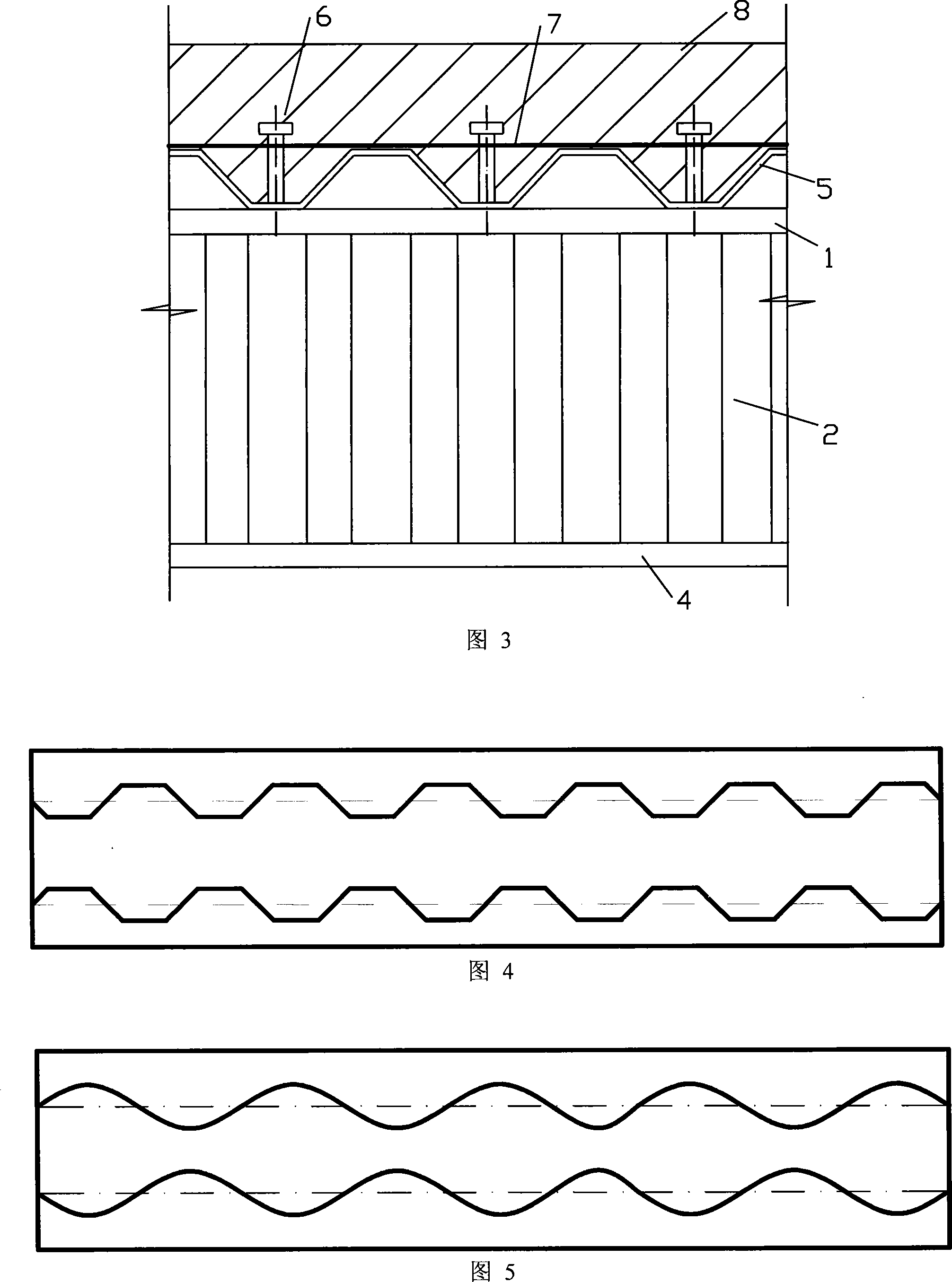
[0037] Example 1: The cross-section shape of the double corrugated web steel box composite girder is composed of the middle web 2, web 3, upper flange 1, and lower flange 4. The upper flange 1 is parallel to the lower flange 4. , the web 2 and the web 3 are perpendicular to the upper flange 1 and the lower flange 4, and the cross-sectional shape of the web 2 and 3 is trapezoidal. The reinforced concrete wing plate 8 is located above the profiled steel plate 5, the profiled steel plate 5 is located above the upper flange 1, the reinforced concrete wing plate 8, the profiled steel plate 5, and the upper flange 1 are fixed by the tack 6, and the transverse reinforcement 7 Welded on the profiled steel plate 5 tops.

[0038] In order to verify the performance of the device, a test piece was made for research. The steel materials in the test pieces are all made of Q235 steel, the thickness of the reinforced concrete wing plate 8 is 100 mm, and C20 concrete is used, the stud 6 is ma...


PUM

PropertyMeasurementUnit
Inclinationaaaaaaaaaa

Abstract

The invention belongs to the technical field of architectural profiles and particularly relates to a double corrugated web steel box composite beam. The sectional shape of the invention is composed of two symmetrically arranged corrugated webs, a top flange and a lower flange. The top flange is parallel with the lower flange, the web is vertical to the top flange and the lower flange, the web and the flange are connected by single-side fillet joint, and the web has periodically repetitive trapezoidal wave or sinusoid wave along the length direction. The top of the composite beam is a reinforced concrete wing plate and a profiling steel plate. The top flange, the reinforced concrete slab and the profiling steel plate are connected each other by male pins, and a transverse reinforcement can be additionally used for the connection between the reinforced concrete wing plate and the profiling steel plate. The invention can replace the traditional hot rolled flange beam, H-beam composite beam and welded steel box composite beam; furthermore, the invention has wider application than the flange beam and the H-beam composite beam, and can realize maximization to be used in special fields and special places, including the construction of wide-span industrial and civilian buildings and wide-span bridges, etc.

Description

technical field [0001] The invention belongs to the technical field of building profiles, in particular to a steel box composite girder with double corrugated webs. Background technique [0002] At present, ordinary hot-rolled I-beams, hot-rolled H-beams and welded H-beam composite beams are commonly used in similar fields. The above-mentioned composite beam is composed of a lower steel beam and an upper reinforced concrete slab through shear connectors to form a force-bearing member. The steel beam is generally made of hot-rolled I-beam, hot-rolled H-beam and welded H-beam. This design can be seen in the patent - Combination Beam (ZL 95195718.X). In addition, there are also steel box girders welded by flat steel plates, which form flat web steel box composite girders with concrete slabs. [0003] Ordinary hot-rolled I-beams and H-beams are hot-rolled in the factory. Due to the limitation of processing technology, their webs must be straight plates. The welded H-shaped st...

Claims


Application Information

Patent Timeline
IPC IPC(8): E04C3/294E04B1/30E04B5/29E04B5/40
Inventor 李国强孙飞飞张哲王卫永王开强王文涛
Owner TONGJI UNIV
Learn More