Silent chain

A chain and pin hole technology, applied in the direction of belt/chain/gear, chain element, transmission chain, etc., can solve the problems of poor stress balance, deterioration of noise, chain wear and elongation, etc., to prevent wear and elongation and suppress noise. , the effect of simplifying the production

Inactive Publication Date: 2009-07-22
TSUBAKIMOTO CHAIN CO
View PDF1 Cites 2 Cited by
  • Summary
  • Abstract
  • Description
  • Claims
  • Application Information

AI Technical Summary

Problems solved by technology

As a result, the load acting on each inner plate is different, so there is a problem that the stress balance between the inner plates is poor, especially the stress balance between the inner plates that are not guide rows is poor.
[0007] Furthermore, since the specific inner plates 14a, 14a disposed on both outermost sides of the non-guide row 16 are intensively subjected to particularly high stress, when the silent chain 11 is wound around the sprockets and bent, there is the following problem: Excessive surface pressure is applied to the inner peripheral surface of the hole 12 and the abutting surface of the connecting pin 19, and both wear and tear, resulting in chain wear, elongation or breakage
[0008] If in order to solve the above problems, the thickness of the two outermost inner plates 14a, 14a of the non-guide row 16 is thicker than that of the other inner plates 14, then there is a problem that the quality of the silent chain itself must be increased and more materials must be used.
[0009] In addition, when the conventional silent chain 11 is used as the timing chain of the engine, due to the above-mentioned problems, there are problems in that the fuel consumption of the engine is poor, the noise performance is also deteriorated, and the environment is adversely affected. , and a high-output engine must use a high-strength, that is, a high-quality silent chain, use more materials, and have poor fuel consumption

Method used


Image

  • Silent chain
  • Silent chain
  • Silent chain

Examples


Embodiment Construction

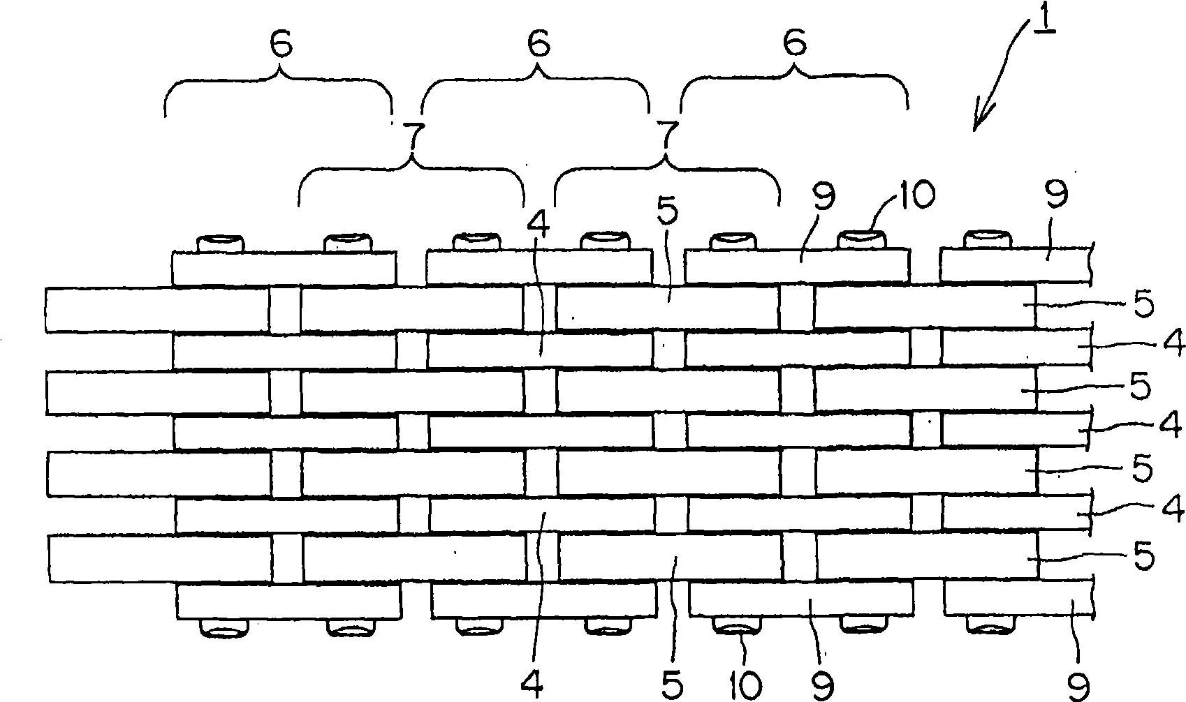
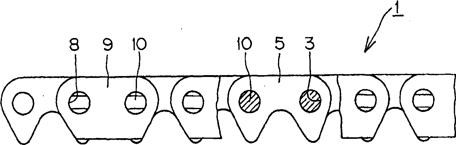
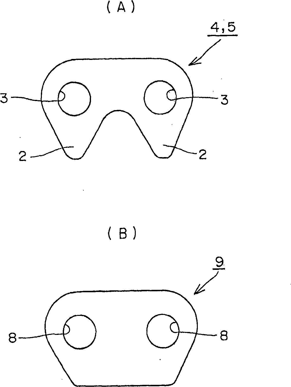
[0037] based on the following Figure 1 to Figure 5 Examples of the present invention will be described. figure 1 is a top view showing part of the silent chain, figure 2 is the main view representing a part of the silent chain, image 3 (A) is the front view of the inner panel, image 3 (B) is the front view of the guide plate, Figure 4 It is an explanatory diagram of the main parts of the silent chain when a low-load tensile tension is applied (initial state), Figure 5 It is an explanatory diagram of the main parts when the silent chain is subjected to a high-load tensile tension so that the connecting pin becomes approximately straight.

[0038] like Figure 1 ~ Figure 3As shown, the silent chain 1 is formed in a ring shape, and a plurality of inner plates 4, 5 with a pair of teeth 2 and a pair of pin holes 3 are arranged in the guide row 6 and the non-guide row respectively in the chain longitudinal direction and alternately staggered positions. row 7, and a guid...


PUM


Abstract

In a silent chain, connecting pins are uniformly contacted with all pin holes of inner plates to prevent the wearing between the special pin holes of inner plates and the connecting pins, and further prevent the wearing elongation of chain even though the high-load stretching tension is applied for the silent chain to bend the connecting pins. The silent chain is circular, the inner plates(4,5) with a pair of pin holes(3) in the guide row(6) and non-guide row(7) are connected to be circular by the connecting pins(10) in the pin holes(3). The connecting pins (10, 10) respectively fixed in a pair of pin holes (8) of guide plate (9) at the outermost side of guide row (6) are bent towards the direction near the central portion (10a). As greater tension is applied to the chain, the bent connecting pins become substantially straight and are brought into substantially uniform contact with pin holes (3) in the plates(4,5).

Description

technical field [0001] The present invention relates to a silent chain used in automobiles (for example, timing chains wound on cam sprockets and crank sprockets of automobile engines), power transmission and conveying equipment of industrial equipment, and the like. Background technique [0002] There is a known silent chain formed in this way: a plurality of inner plates with a pair of teeth and a pair of pin holes are respectively arranged in the guide row and the non-guide row, and the guide plates are arranged on the two outermost sides of the guide row and connected by The pins are connected in an annular shape (for example, refer to Patent Document 1.). [0003] Image 6 An example of a conventional silent chain 11 is shown. Image 6 It is an explanatory diagram of main parts of the silent chain 11 when a low-load tensile tension acts on the silent chain (initial state). With regard to the silent chain 11, inner plates 13, 14 having a pair of teeth (not shown) and a ...

Claims


Application Information

Patent Timeline
Patent Type & Authority Applications(China)
IPC IPC(8): F16G13/00
CPCF16G13/08F16G13/04
Inventor 户原隆
Owner TSUBAKIMOTO CHAIN CO
Why Eureka
Try Eureka