Double-direction torque transmission device
A torque transmission device, bidirectional technology, applied in the direction of transmission, belt/chain/gear, mechanical equipment, etc., can solve the problems of increasing the complexity and cost of the device, and achieve the effect of simplifying the structure and reducing the cost
- Summary
- Abstract
- Description
- Claims
- Application Information
AI Technical Summary
Problems solved by technology
Method used
Image
Examples
no. 1 example
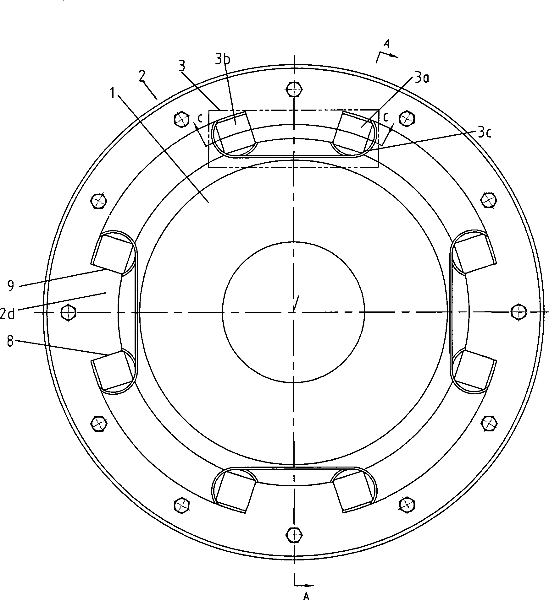
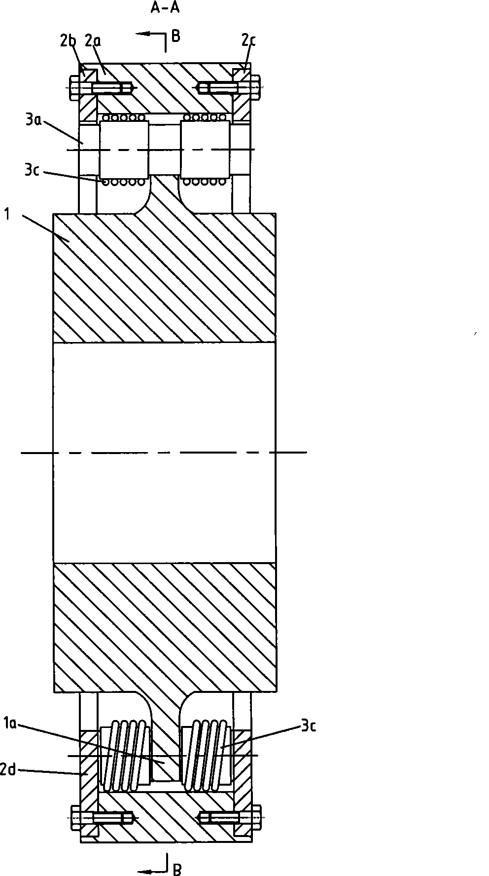
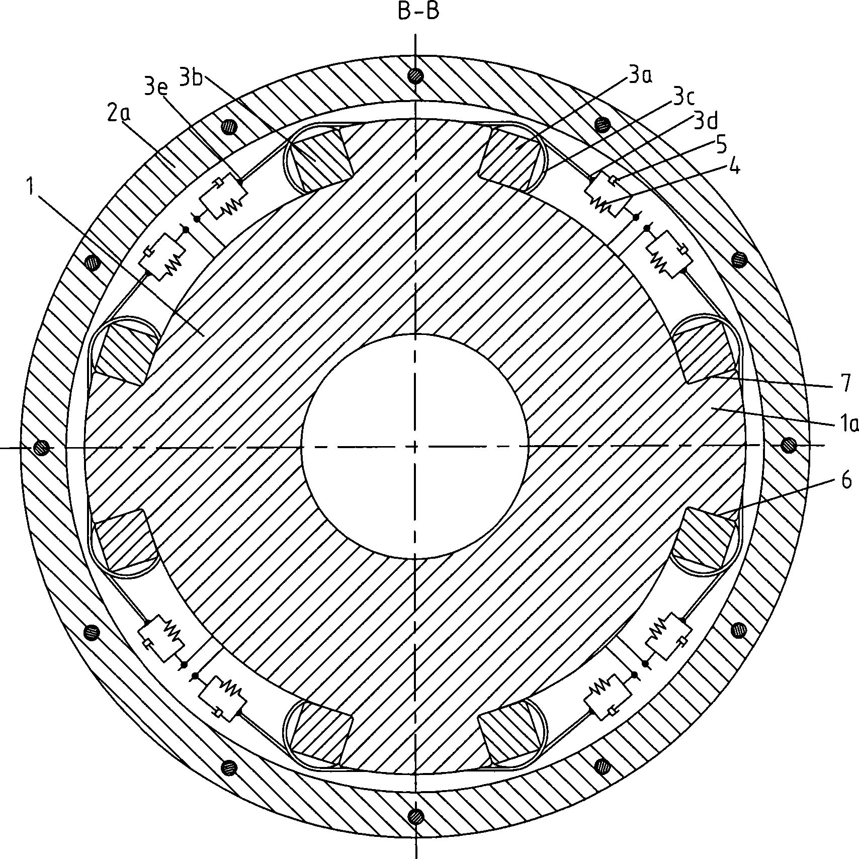
[0027] Such as figure 1 , figure 2 , image 3 and Figure 4 As shown, the bidirectional torque transmission device according to the first embodiment of the present invention includes a first transmission member 1 , a second transmission member 2 and windings 3 , and the number of windings 3 in this embodiment is four. Such as figure 2 As shown, the second transmission member 2 is composed of a transmission ring 2a and a left transmission plate 2b and a right transmission plate 2c located on both sides of the transmission ring 2a, and the left transmission plate 2b and the right transmission plate 2c are fixedly connected to the transmission ring 2a by screws ;
[0028] Such as Figure 4 As shown, each phase winding 3 includes a first winding column 3a, a second winding column 3b, and a flexible member 3c. A winding column 3a and a second winding column 3b, the "sequential winding" means that the flexible member 3c is wound from the first winding column 3a to the second...
no. 2 example
[0038] Such as Figure 5 , Figure 6 , Figure 7 and Figure 8 As shown, the difference between the second embodiment of the present invention and the first embodiment is that, in order to further improve the bearing capacity of the bidirectional torque transmission device, a six-phase winding 32 is used; and as Figure 7 As shown, each winding 32 is connected together through the same flexible member 32c, that is, the flexible member 32c in each phase winding 32 is a whole; the two ends of the integral flexible member 32c are directly fixedly connected to the first transmission member 12 or the second transmission member 22.
[0039] The first transmission member 12 is respectively provided with six outwardly extending bosses 12a on both sides of itself, and the front and rear surfaces of the bosses 12a along the circumferential direction are respectively used as a positive force application surface 62 and a reverse force application surface 72 , the left transmission pla...
no. 3 example
[0043] Such as Figure 9 As shown, it is the third embodiment of the present invention. The difference from the second embodiment is that the first winding post 33a and the second winding post 33b are composed of a mandrel 34, a bearing 35 and a pulley 36, wherein the bearing 35 sets Placed on the mandrel 34 , the pulley 36 is sleeved on the bearing 35 , and the flexible member 33 c is wound on the pulley 36 . Intermediate pieces 0 are provided at both ends of the mandrel 34 of the first winding post 33 a and the second winding post 33 b , that is, four intermediate pieces 0 are used in each phase winding. When the first transmission member applies a positive torque to the second transmission member, the positive force-applying surface 63 and the positive force-receiving surface 83 press the intermediate piece 0 on the first winding post 33a and the second winding post 33b respectively. , when the first transmission member applies a reverse torque to the second transmission m...
PUM
 Abstract
Description
Claims
Application Information
 - R&D
- Intellectual Property
- Life Sciences
- Materials
- Tech Scout
- Unparalleled Data Quality
- Higher Quality Content
- 60% Fewer Hallucinations
Browse by: Latest US Patents, China's latest patents, Technical Efficacy Thesaurus, Application Domain, Technology Topic, Popular Technical Reports.
© 2025 PatSnap. All rights reserved.Legal|Privacy policy|Modern Slavery Act Transparency Statement|Sitemap|About US| Contact US: help@patsnap.com


