
Data transmission method based on flow table

A technology of data transmission and flow table, applied in the field of data transmission, can solve problems such as difficulties, achieve the effect of overcoming traffic bottlenecks and promoting maximization of efficacy

Active Publication Date: 2020-08-25
CHINA UNIONPAY
View PDF5 Cites 0 Cited by
  • Summary
  • Abstract
  • Description
  • Claims
  • Application Information

AI Technical Summary

Problems solved by technology

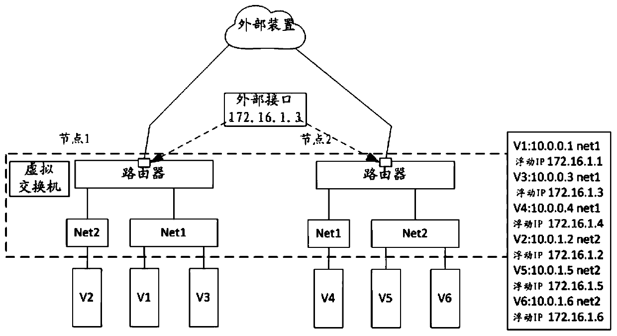
Therefore, it is still difficult to accurately send external data packets back to the corresponding local virtual machines (V1-V6) that do not have floating IPs via nodes (node ​​1, 2) and then via subnets (Net1, Net2)

Method used


Image

  • Data transmission method based on flow table
  • Data transmission method based on flow table
  • Data transmission method based on flow table

Examples


Embodiment Construction

[0027] In the following description, specific details are set forth in order to provide a thorough understanding of the present invention. It will be apparent, however, to one skilled in the art that embodiments of the invention may be practiced without these specific details. In the present invention, specific numerical references such as "first element", "second means" and the like may be made. However, specific numerical references should not be construed as necessarily obeying their literal order, but rather that "first element" is different from "second element".

[0028] The specific details set forth herein are exemplary only, and the specific details may vary while remaining within the spirit and scope of the invention. The term "coupled" is defined to mean either directly connected to a component or indirectly connected to a component via another component.

[0029] Preferred embodiments of methods, systems and devices adapted to implement the present invention are ...


PUM


Abstract

The present invention relates to a data transmission method based on a flow table, comprising: delivering the flow table to a first virtual switch, so that the external interface corresponding to the first virtual switch is configured to receive an ARP request from an external device; the first virtual switch Generate the corresponding ARP response to the ARP request based on the flow table; the external interface receives the data packet from the external device; determine whether the destination virtual machine of the data packet is in the physical machine corresponding to the first node; if the destination virtual machine is in a different physical machine than the first node For the physical machine corresponding to the second node, the first virtual switch forwards the data packet to the second virtual switch. It can reliably and efficiently realize the two-way transmission of data packets between each terminal and an external device, and enable the distributed routing communication solution to maximize its effectiveness.

Description

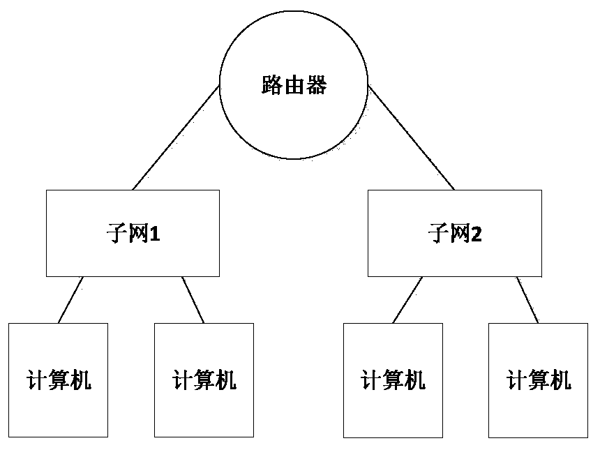
technical field [0001] The present invention relates to the technical field of data transmission, and more specifically, relates to a data transmission method based on a flow table. Background technique [0002] A router (Router) is used to connect multiple logically separated networks. The so-called logical network represents a separate network or a subnet. When data is transferred from one subnet to another, it can be done through the router's routing function. Such as figure 1 shown. [0003] Communication between computers on different subnets must be done through a router. In the network implementation of software SDN, the routing function is realized through the mechanism of software, which can be divided into two forms: centralized routing and distributed routing. [0004] (1) Centralized routing [0005] In the centralized routing mechanism, east-west traffic (traffic between different networks) and north-south traffic (traffic between the internal network and t...

Claims


Application Information

Patent Timeline
Patent Type & Authority Patents(China)
IPC IPC(8): H04L12/721H04L12/911H04L29/12
CPCH04L45/44H04L47/825H04L61/103
Inventor 袁航周雍恺吴金坛祖立军何东杰
Owner CHINA UNIONPAY
Learn More