
DSC meter with visualization function

A technology of differential scanning calorimetry and function, which is applied in the field of differential scanning calorimeter, can solve the problems of unavailable, researched, and limited material temperature characteristics, and achieve the effect of low operating temperature, simple operation, and compact structure

Inactive Publication Date: 2011-06-08
SUN YAT SEN UNIV
View PDF0 Cites 0 Cited by
  • Summary
  • Abstract
  • Description
  • Claims
  • Application Information

AI Technical Summary

Problems solved by technology

However, using these two methods independently requires separate testing of the sample. Due to the difference in the test environment, the two data results are often not well matched, thus limiting the comprehensive study of the temperature characteristics of the material.

Method used


Image

  • DSC meter with visualization function
  • DSC meter with visualization function
  • DSC meter with visualization function

Examples


Embodiment Construction

[0023] The present invention will be described in detail below in conjunction with the accompanying drawings.

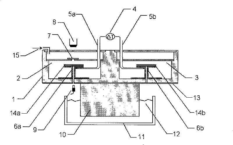
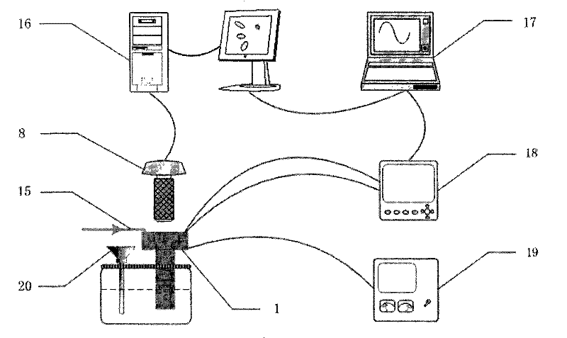
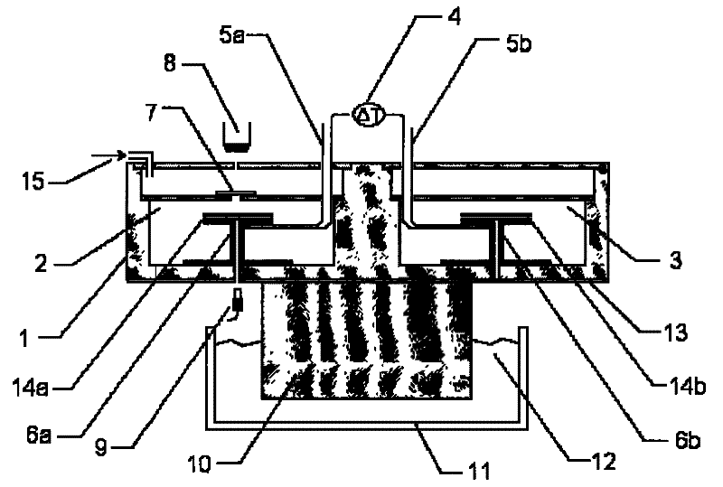
[0024] Such as figure 1 and figure 2 As shown, a differential scanning calorimeter compatible with visualization function includes a DSC workbench 1 provided with a sample cell 2 and a reference cell 3, and a device set in the sample cell 2 for carrying the sample and transferring heat flow with the sample. The first heat flow detection part 6a, the second heat flow detection part 6b set in the reference cell 3 to carry the reference object and transfer heat flow with the reference object, respectively heat up and cool down the two heat flow detection parts 6a, 6b The controlled temperature control device, the temperature recorder 18 connected to the two heat flow detection components 6a, 6b respectively through the thermocouple wires 5a, 5b, also includes a microscope camera system and an image acquisition system 16, and the microscope camera system passes through...


PUM


Abstract

The invention discloses a differential scanning calorimeter, which is compatible with visualization and comprises a worktable, a first heat current detection part, a second heat current detection part, temperature control equipment, a temperature-recording instrument, a microscope image pickup system and an image acquisition system; wherein, the worktable is provided with a sample cell and a reference cell. The first heat current detection part is arranged in the sample cell and used for bearing samples and transmitting heat flux with the samples. The second heat current detection part is arranged in the reference cell and is used for bearing reference compound and transmitting heat flux with the reference compound. The temperate control equipment respectively controls the heating up and temperature reduction of the two heat current detection parts. The temperature-recording instrument is respectively connected with the two heat current detection parts by a thermocouple wire. The microscope image pickup system observes the microstructure of the samples by a sample observation window arranged on the sample cell and acquires and records the microstructure variation of the sample by the image acquisition system. The differential scanning calorimeter can monitor and acquires the structure variation information of the sample while measuring the heat flow when the samples change phase, and increases the synchronicity and integrity of real-time analysis detecting of the samples.

Description

technical field [0001] The invention relates to a differential scanning calorimeter compatible with visualization function. Background technique [0002] Differential Scanning Calorimetry (DSC) is capable of measuring the heat flow when a sample changes phase with temperature. When the sample crystallizes, the heat flow curve shows a corresponding exothermic peak, and when the sample melts, the heat flow curve shows a corresponding absorption peak. The heat absorbed or released by the sample during phase transition can be deduced from the areas of these peaks. However, differential scanning calorimetry can only quantitatively reflect the total heat released or absorbed by the sample during the phase transition process, but cannot give detailed information on the structural changes of the sample itself. [0003] Microscopy is a commonly used observation method for the study of the microstructure of materials, such as polymer materials, aqueous solutions, cells or biological...

Claims


Application Information

Patent Timeline
Patent Type & Authority Patents(China)
IPC IPC(8): G01N25/20G01N21/84
Inventor 吕树申王海燕
Owner SUN YAT SEN UNIV
Learn More