

Brightness adjustable luminous indicator
A signage and brightness adjustment technology, applied in the field of municipal transportation, can solve the problems of inconvenience to passers-by and limited luminous energy
- Summary
- Abstract
- Description
- Claims
- Application Information
AI Technical Summary
Problems solved by technology
Method used
Image

Examples
Embodiment 1
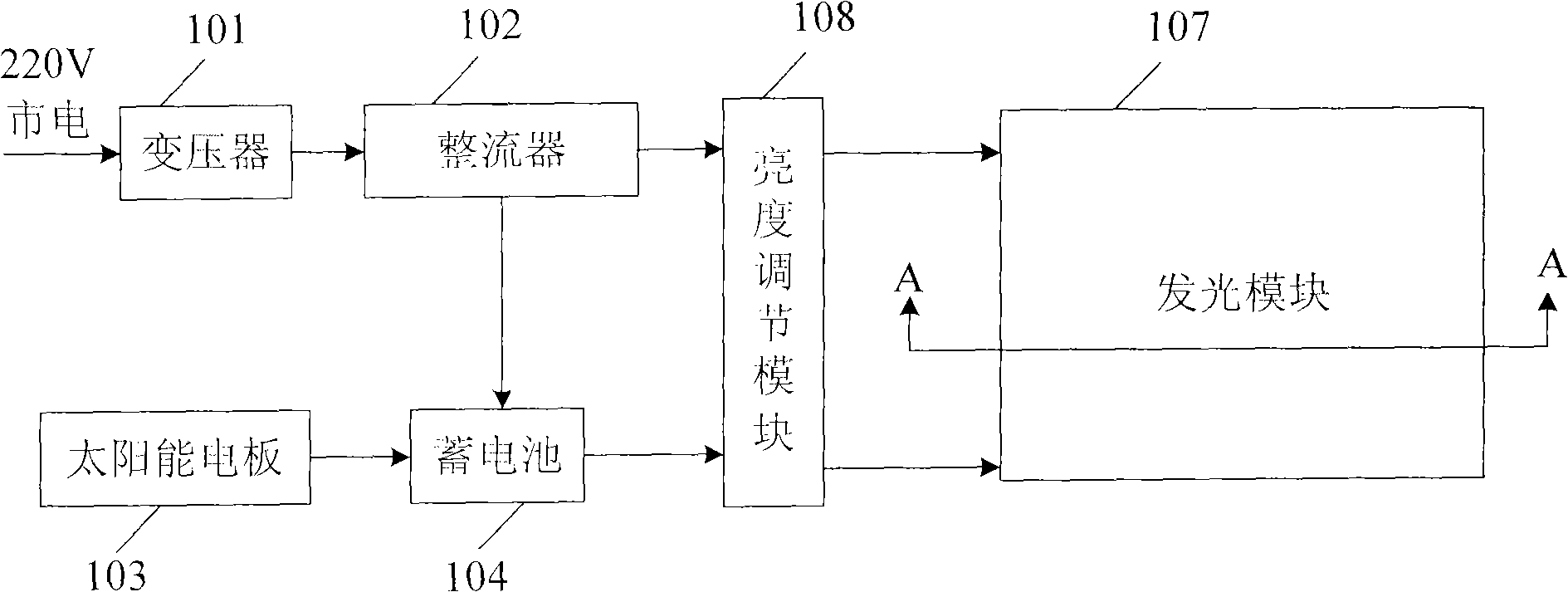
[0043] Such as figure 1 As shown, the present invention provides a road light-emitting sign whose brightness can be automatically adjusted, including: a power supply module, a brightness adjustment module 108 and a light-emitting module 107. Control to provide constant current power to the light emitting module 107 . The brightness adjustment module 108 is used to control the brightness of the light emitting module 107 to be adjusted in time according to the intensity of ambient light.
[0044] For example, it is judged that when the ambient light illuminance is strong, the light emitting module 107 is made to emit light with high brightness, and when the ambient light illuminance is weak, the light emitting module 107 is made to emit light with low brightness.
[0045] For example, the control program is preset in the brightness adjustment module 108. When the ambient light illuminance reaches more than 100,000 LUX (outdoor on a sunny day in summer), the light emitting modul...
Embodiment 2
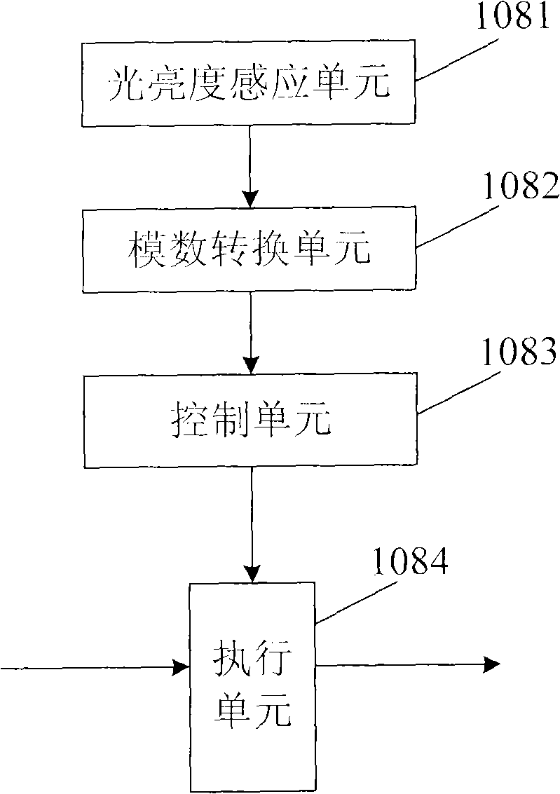
[0047] On the basis of Embodiment 1, this embodiment preferably adopts the following scheme to realize the brightness adjustment function of the brightness adjustment module 108, such as figure 2 As shown, the brightness adjustment module 108 includes a brightness sensing unit 1081, which is installed outside the light emitting module 107 in the open air, and is used to monitor changes in ambient light illumination. The analog quantity of ambient light and illuminance monitored by the sensing unit 1082 is converted into a digital signal that the system can recognize, and the control unit 1083 is connected with the analog-to-digital conversion unit 1082, and is used to output different control signals to the execution unit 1084 according to the above digital signal, and control the execution unit 1084 outputs different brightness data to the light-emitting module 107. In this way, the brightness of the light-emitting module 107 changes in real time under the control of the cont...
Embodiment 3
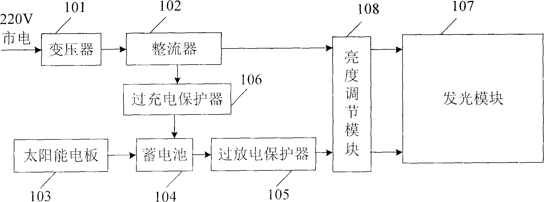
[0051] On the basis of the above-mentioned embodiments, in order to improve the safety and stability of the circuit operation and ensure that the sign can work normally in the case of power supply interruption, an emergency power supply module can also be set in the circuit, including the battery 104 and solar energy The electric panel 103, the solar electric panel 103 uses solar energy to charge the storage battery.
[0052] An example such as image 3 As shown, an overcharge protection device 106 is provided between the rectifier 102 and the battery 104 to stop charging the battery 104 when the voltage reaches the highest value. The over-discharge protection device 105 is used to stop the external discharge of the battery when the voltage of the battery reaches a minimum value. In this way, the battery can be protected and its service life can be extended.
PUM
 Abstract
Description
Claims
Application Information