Micro-wave oven

A microwave oven and microwave technology, applied in the field of microwave ovens, can solve the problems of high production cost, large floor space, and complex structure, and achieve the effects of small floor space, high heating efficiency, and convenient operation

Inactive Publication Date: 2009-07-29
GUANGDONG GALANZ GRP CO LTD
View PDF2 Cites 26 Cited by
  • Summary
  • Abstract
  • Description
  • Claims
  • Application Information

AI Technical Summary

Problems solved by technology

Its structure is complex, the production

Method used


Image

  • Micro-wave oven
  • Micro-wave oven
  • Micro-wave oven

Examples


Embodiment Construction

[0016] The present invention will be further described below in conjunction with the accompanying drawings and embodiments.

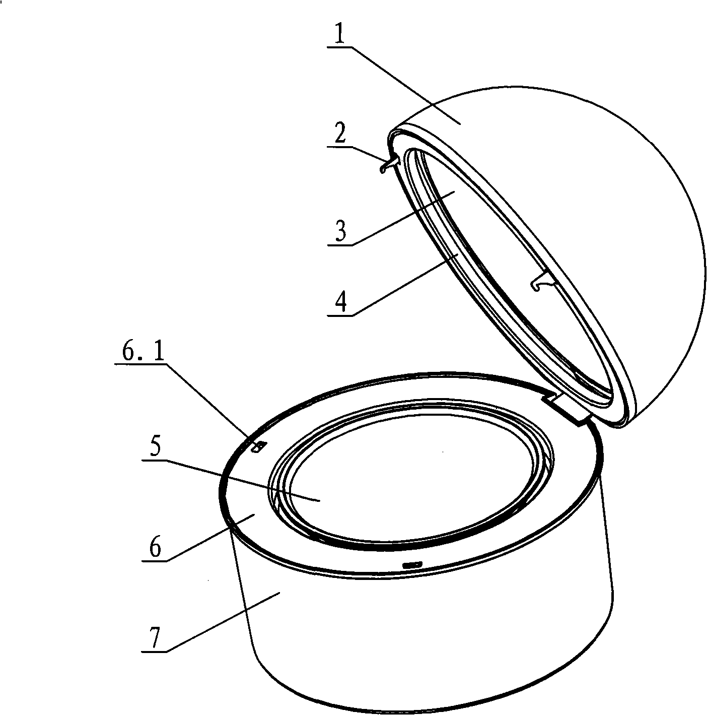
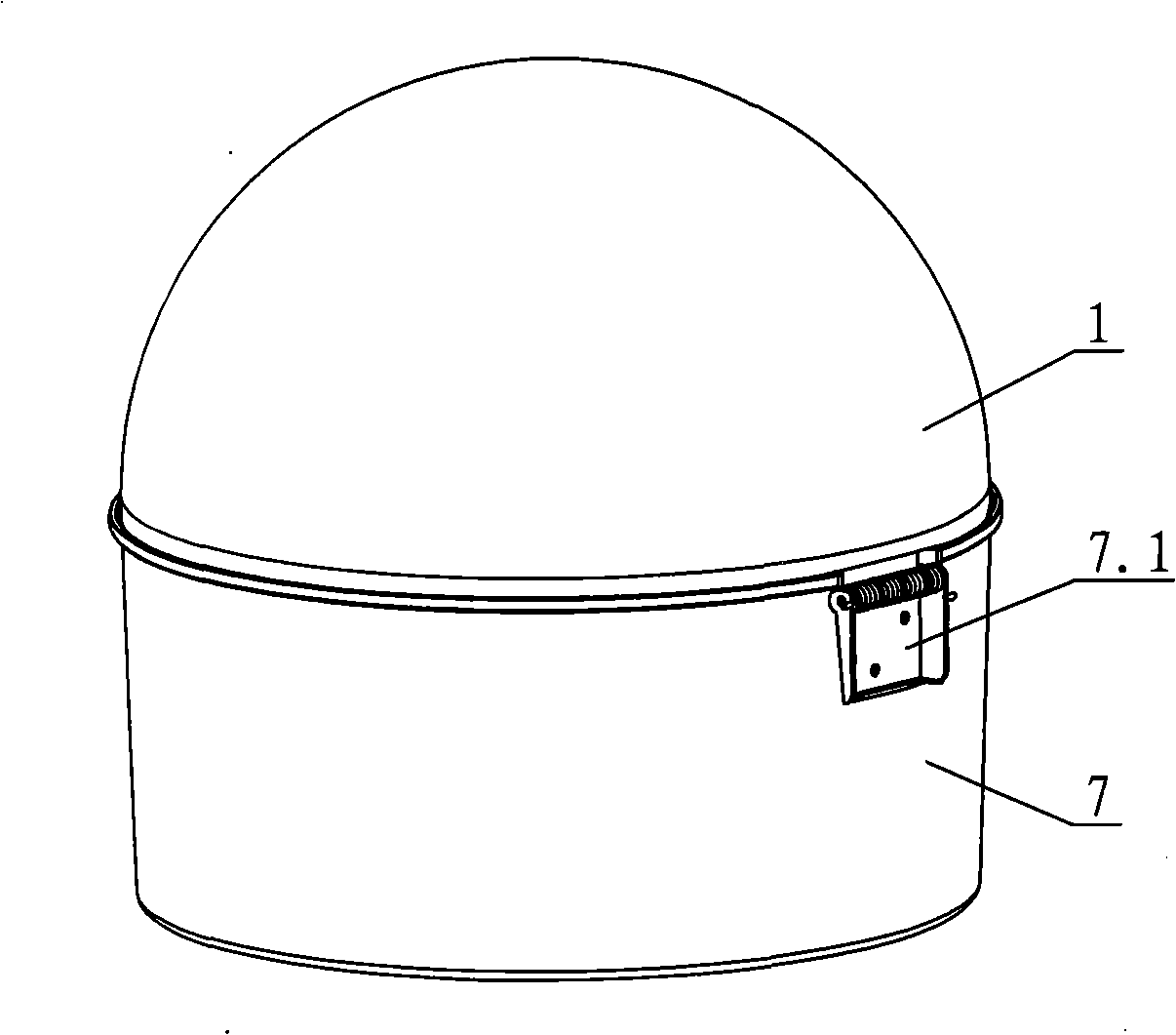
[0017] see Figure 2-Figure 5 , the microwave oven comprises a furnace seat 7, a microwave generating unit and a cooking chamber, the cooking chamber is composed of a supporting mechanism and a microwave shielding cover 1, the microwave shielding cover is arranged above the supporting mechanism, and the furnace seat 7 is arranged below the supporting mechanism; the microwave generating unit is arranged In the hob, the generated microwaves are emitted from the support mechanism into the cooking cavity. The support mechanism includes a furnace cover 6 and a support plate 5. The outer edge of the furnace cover is connected to the top of the furnace seat 7. The center of the top surface is provided with a recess corresponding to the support plate. The support plate is plate-shaped and is arranged on the recess.

[0018] The microwave shielding cover 1 is h...


PUM


Abstract

A microwave oven comprises an oven seat, a microwave generating unit and a cooking cavity. The cooking cavity is composed of a cavity enclosed by a supporting mechanism arranged on the oven seat and a microwave shielding cover; the microwave shielding cover can be opened or locked relative to the oven seat and/or the supporting mechanism; the supporting mechanism comprises an oven cover on the oven seat; the oven cover is tabulate, discal or kettle-shaped and the surface of the oven cover is equipped with microwave through holes corresponding to a microwave emitting area. The microwave oven cooking cavity of the invention directly consists of the supporting mechanism for holding food and the microwave shielding cover; the oven seat equipped with the microwave generating unit is positioned below the cooking cavity; the microwave from the microwave generating unit is emitted to the cooking cavity from bottom to top to heat the materials in the cooking cavity, thus breaking through the design of the traditional microwave ovens. In addition, the heated materials are put on a supporting plate of the supporting mechanism from the upward side, thereby facilitating the operation and cleaning. The microwave oven features simple and reasonable structure, easy manufacturing and processing, high heating efficiency and small floor area.

Description

technical field [0001] The invention relates to a microwave oven. Background technique [0002] Traditional microwave ovens such as figure 1 As shown, in general, its main structure is an oven cavity 21 and an oven door 22, and the microwaves generated by the magnetron are emitted into the oven cavity, and food is placed in the oven cavity. The furnace cavity is formed by a layer of metal wrapping, the magnetron 20 is placed on the side of the furnace cavity, and the magnetron emits microwaves from the side of the furnace cavity into the furnace cavity. An oven door is arranged on the front of the oven cavity, and the oven door is opened to put food in from the oven door. The cavity of the microwave oven accounts for most of the overall volume of the microwave oven. This main body design limits the development of the microwave oven, and many technologies are difficult to be applied to this design. To a certain extent, this traditional design hinders the development of mic...

Claims


Application Information

Patent Timeline
IPC IPC(8): F24C7/02
Inventor 王守国区宗尹廖波李志刚
Owner GUANGDONG GALANZ GRP CO LTD
Why Eureka
Try Eureka