LCD panel

A technology of liquid crystal display panels and pixel columns, applied in static indicators, nonlinear optics, instruments, etc., can solve the problems of reduced production efficiency and increased production costs of liquid crystal display panels 400, and achieve improved image color shift and reduced layout area and production cost, the effect of reducing the number of use

Inactive Publication Date: 2009-07-29
CHUNGHWA PICTURE TUBES LTD
View PDF0 Cites 3 Cited by
  • Summary
  • Abstract
  • Description
  • Claims
  • Application Information

AI Technical Summary

Problems solved by technology

However, this method will increase the production cost of the liquid crystal display panel 400 and reduce the production efficiency.

Method used


Image

  • LCD panel
  • LCD panel
  • LCD panel

Examples


Embodiment Construction

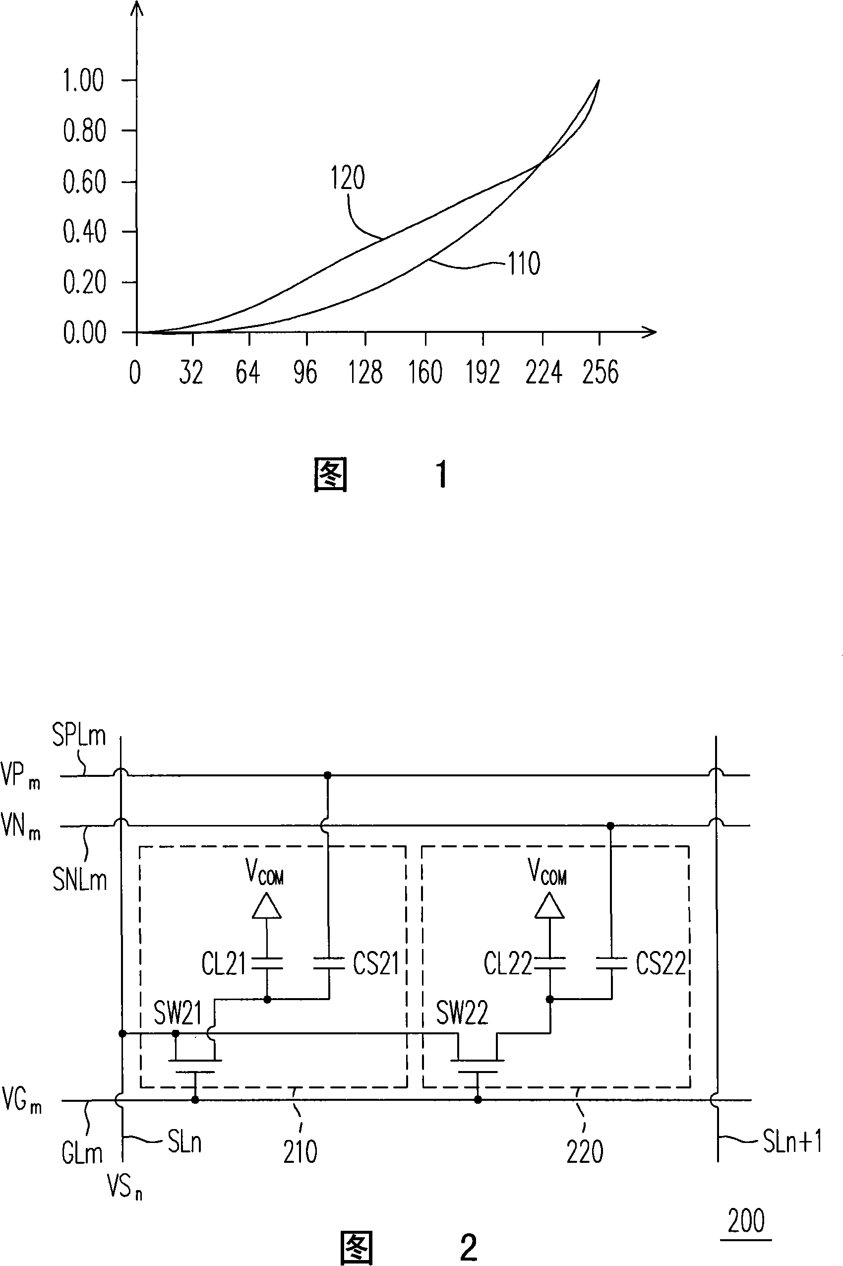
[0048] The main technical feature of the present invention is to divide a pixel into two sub-pixels, and adjust the gray scale of one of the sub-pixels to improve the phenomenon of image color shift, thereby effectively reducing the number of peripheral signal wirings used. The liquid crystal display panel of the present invention will be illustrated below, but it is not intended to limit the present invention. Those skilled in the art can slightly modify the following embodiments according to the spirit of the present invention, but they still belong to the scope of the present invention.

[0049] Before explaining the liquid crystal display panel, the pixels in the liquid crystal display panel will be explained below. Figure 5 It is a schematic structural diagram of a pixel 500 according to an embodiment of the present invention. Please refer to Figure 5 The pixel 500 includes sub-pixels 510 and 520 , and the sub-pixel 510 includes a switch SW51 , a liquid crystal capacit...


PUM


Abstract

The invention discloses a liquid crystal display panel, which improves the phenomenon of color divergence by dividing a pixel into two sub-pixels and using a memory voltage signal to adjust the gray scale of one sub-pixel. The liquid crystal display panel only requires one memory voltage signal, thus effectively reducing the use number of the circumferential signal wiring, and further reducing the layout area and the production cost of the liquid crystal display panel.

Description

technical field [0001] The present invention relates to a liquid crystal display panel, and in particular to a liquid crystal display panel which utilizes a single storage voltage signal to improve the image color shift of each pixel. Background technique [0002] In order to make the liquid crystal display (LCD) have better display quality, the current liquid crystal display is developing towards the characteristics of high contrast, small color shift, high brightness, high color saturation, fast response and wide viewing angle. In terms of wide viewing angle technology, a multi-domain vertically aligned (MVA) liquid crystal display is generally used. However, when the user watches the liquid crystal display from a larger viewing angle, the seen image usually has a phenomenon of color washout, which is the color washout of the image. Among them, the reason for the formation of image color shift is that, as shown in FIG. 1 , the schematic diagram of the gamma curve of the e...

Claims


Application Information

Patent Timeline
Patent Type & Authority Applications(China)
IPC IPC(8): G02F1/1362G09G3/36
Inventor 陈建宏许庭彰王贤军
Owner CHUNGHWA PICTURE TUBES LTD
Why Eureka
Try Eureka