Method and control device for stopping a motor vehicle without jolting

A technology of motor vehicles and braking devices, applied in the direction of automatic starting devices, brakes, etc., can solve the problem of not being able to be felt

Inactive Publication Date: 2009-07-29
LUCAS AUTOMOTIVE GMBH
View PDF0 Cites 5 Cited by
  • Summary
  • Abstract
  • Description
  • Claims
  • Application Information

AI Technical Summary

Problems solved by technology

Thus, the soft stop function in the electrohydraulic braking system does not lend itself to being felt in the response characteristics of the brake pedal

Method used


Image

  • Method and control device for stopping a motor vehicle without jolting
  • Method and control device for stopping a motor vehicle without jolting

Examples


Embodiment Construction

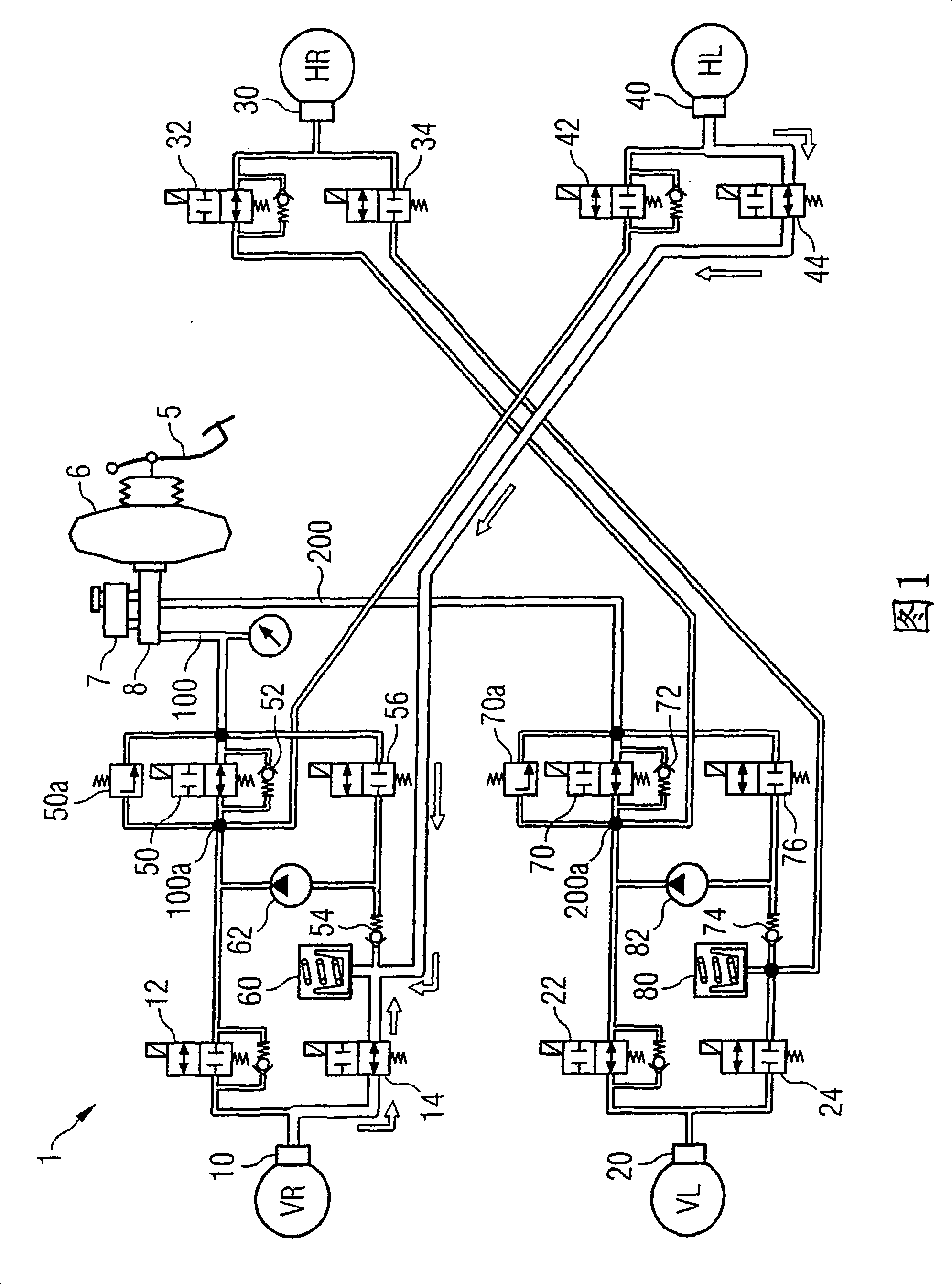
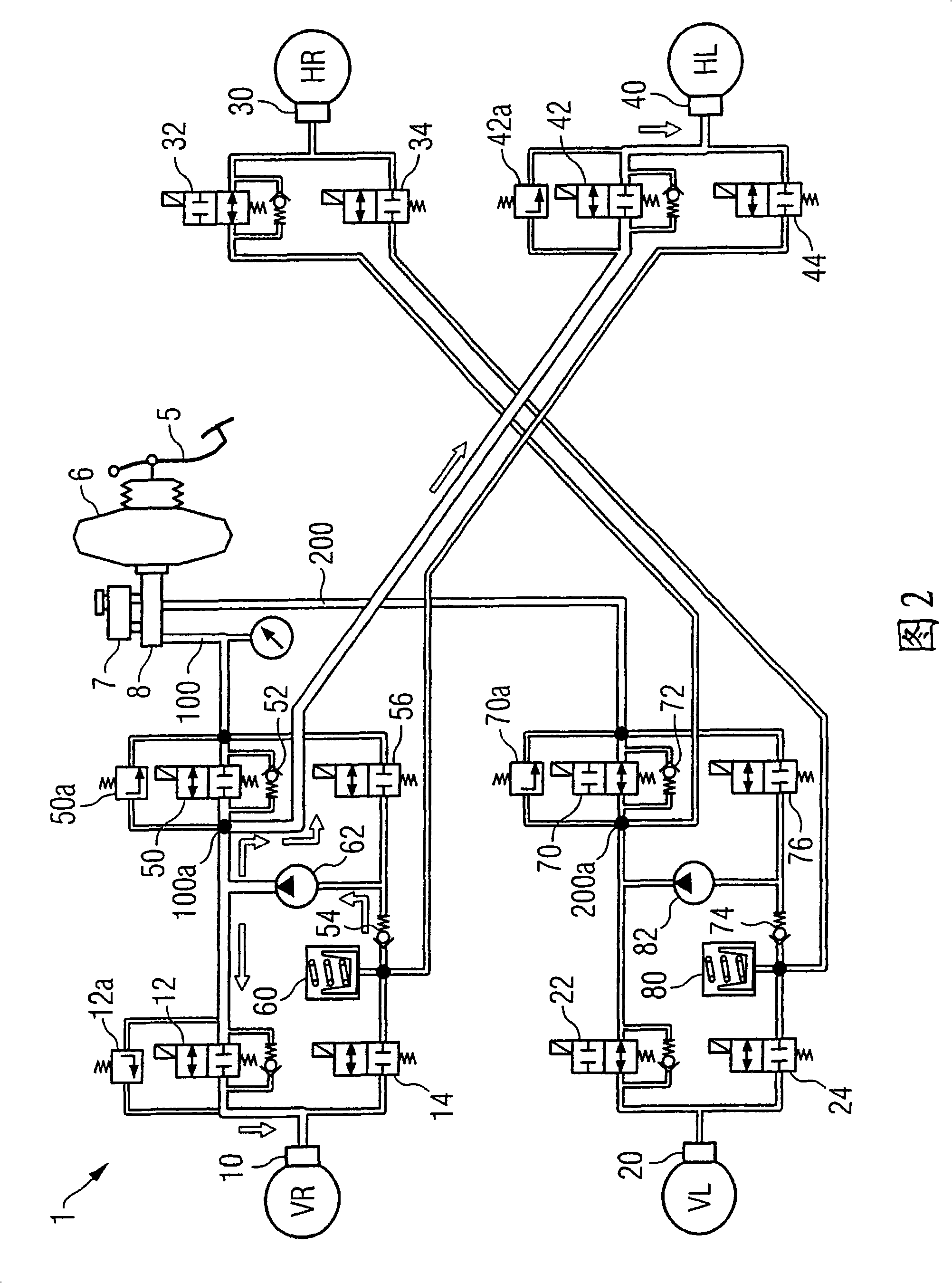
[0024] In FIGS. 1 and 2 , an embodiment of a control unit implemented in a braking system 1 and suitable for implementing the method according to the invention for stopping a motor vehicle without jolting is schematically shown. In both figures, the same reference numerals designate the same components of the brake system 1 . Since FIGS. 1 and 2 represent two different operating states of the same braking system 1 , only the structure and individual components of the braking system 1 will be described with reference to FIG. 1 .

[0025] The brake system 1 shown in FIG. 1 comprises two diagonally running brake circuits 100 , 200 . A brake circuit 100 connects the brake device 10 of the right front wheel and the brake device 40 of the left rear wheel to the pedal force actuation devices 5, 6, 7, 8 for supply of pressurized hydraulic fluid. A brake circuit 200 connects the braking device 20 of the left front wheel and the braking device 30 of the right rear wheel to the devices ...


PUM


Abstract

A method for stopping a motor vehicle without jolting is described which is characterized by the fact that a sum of the hydraulic fluid pressures which are generated by the brake system (1) which can be activated by foot force and which act on the brake devices (10, 20, 30, 40) of the motor vehicle is reduced by 30% to 70% during the stopping process independently of the driver and as a function of a variable which relates to the speed of the vehicle.

Description

technical field [0001] The invention relates to a method for stopping a motor vehicle without jolting and a control unit for the method. Background technique [0002] To date, the function of stopping a motor vehicle without shaking (“soft stopping”) has been realized only in so-called electrohydraulic braking systems. [0003] In electro-hydraulic or power-actuated braking systems, the driver's request at the brake pedal is detected by a sensor and supplied as an electrical signal to an electronic controller that controls an electric brake pressure generator ("brake-by-wire "model). In order to be able to brake the motor vehicle with minimal deceleration even in the event of a failure of the vehicle's electrical system, the electrohydraulic braking system also features redundant hydraulic emergency braking, which acts directly on the wheels without any electronic control on the brake. In the case of this hydraulic emergency braking function, a direct connection ("push th...

Claims


Application Information

Patent Timeline
Patent Type & Authority Applications(China)
IPC IPC(8): B60T7/12B60T8/00
CPCB60T8/4872B60T8/00B60T2230/04B60T8/1766B60T7/12
Inventor 约瑟夫·克内希特格斯
Owner LUCAS AUTOMOTIVE GMBH
Why Eureka
Try Eureka