Refrigerator

A refrigerator and a shelf technology, applied in the field of refrigerators, can solve the problems of the shelf falling off, being complicated, and difficult to realize a complex mechanism, and achieving the effects of preventing the shelf from falling off, uniform temperature, and improving storage efficiency

Inactive Publication Date: 2009-07-29
SHARP KK
View PDF1 Cites 6 Cited by
  • Summary
  • Abstract
  • Description
  • Claims
  • Application Information

AI Technical Summary

Problems solved by technology

[0008] However, as shown in Patent Document 1, the mechanism for slidably connecting the front shelf with respect to the rear shelf is relatively complicated, and there are problems in that the manufacturing process becomes complicated and the cost increases.
[0009] Especially when a glass plate that is difficult to process into a complicated shape is used as a shelf in the storage room, ther

Method used


Image

  • Refrigerator
  • Refrigerator
  • Refrigerator

Examples


no. 1 approach

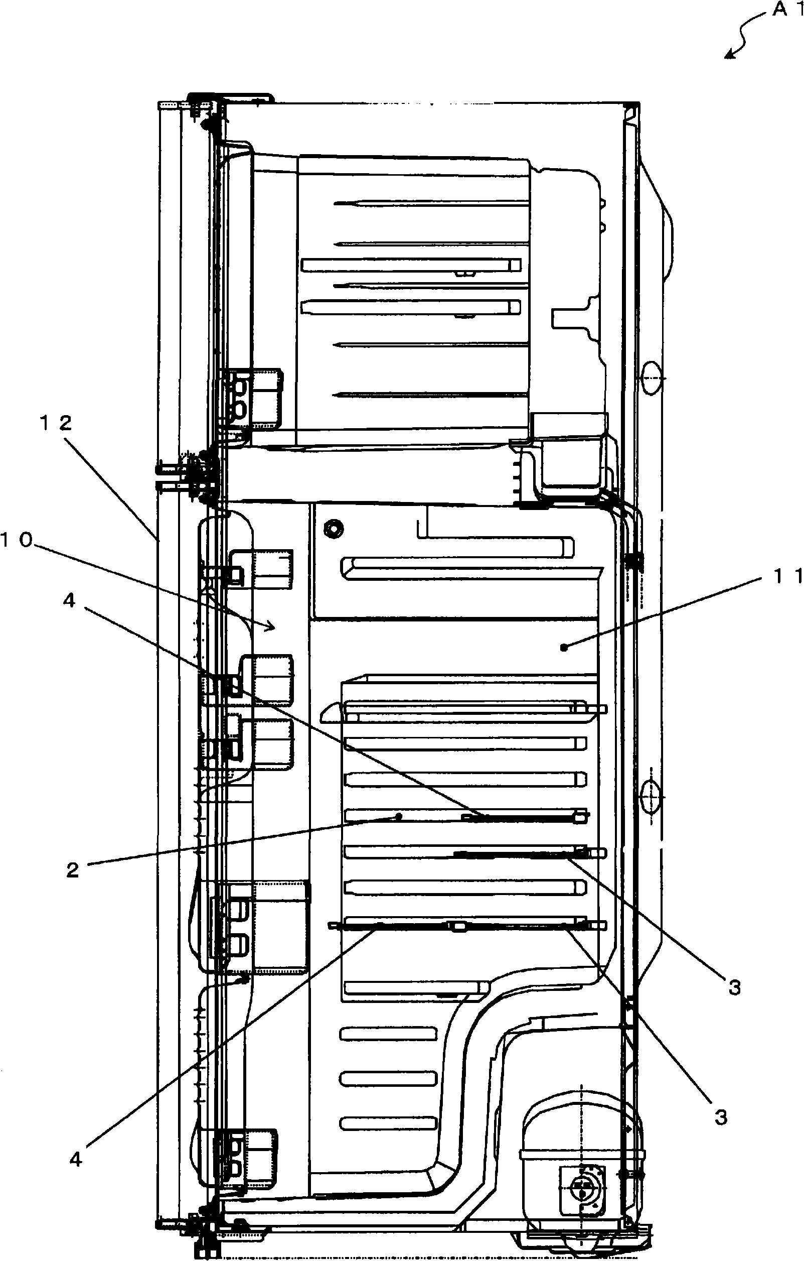
[0085] First, refer to figure 1 The schematic structure of the whole refrigerator A1 which concerns on the 1st Embodiment of this invention is demonstrated with the side cross-sectional view shown. in addition, figure 1 In the figure, the left side in the figure is the front direction (near side) of refrigerator A1, and the right side is the back direction (back side) of refrigerator A1.

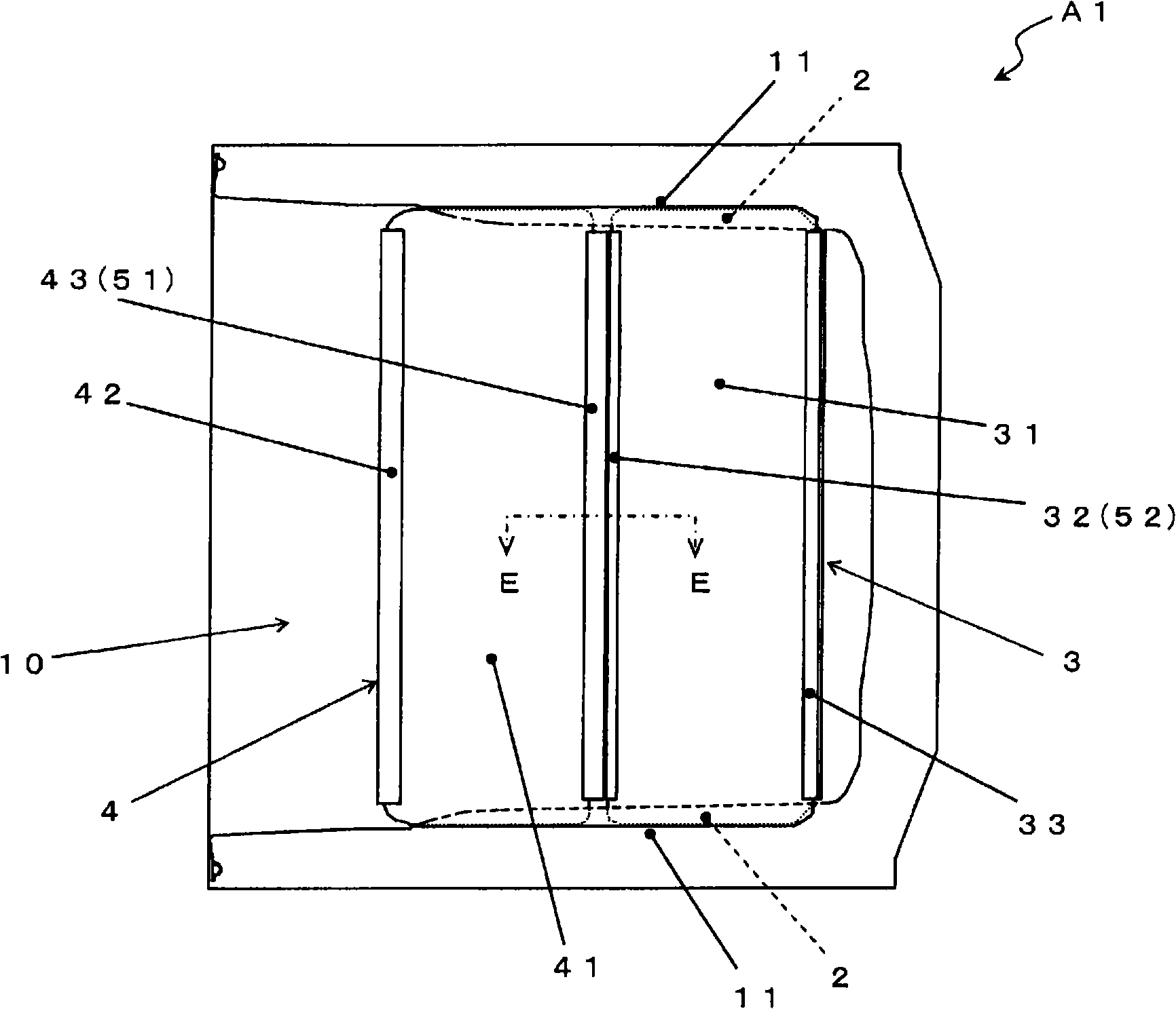
[0086] Such as figure 1 As shown, refrigerator A1 according to the first embodiment of the present invention has storage chamber 10 for storing food (an example of object to be cooled) inside. The storage chamber 10 is surrounded by partition walls except for the front, and a door 12 forming the exterior of the refrigerator A1 is provided on the front side so as to be openable and closable.

[0087] In addition, the refrigerator A1 includes a plurality of shelves 3 and 4 that partition the interior of the storage chamber 10 in the vertical direction. The shelves 3 and 4 are supported at ...

no. 2 approach

[0119] Next, refer to Figure 5 The top sectional view of the shown storage chamber 10, Figure 6 and Figure 7 A side sectional view and a front sectional view of the shown shelf engaging mechanism X2 are used to describe the refrigerator A2 according to the second embodiment of the present invention. In addition, in each figure, the same code|symbol is attached|subjected to the same component as the member included in refrigerator A1.

[0120] The refrigerator A2 has the same structure as the above-mentioned refrigerator A1, and includes the shelf engaging mechanism X2 whose basic structure is the same as that of the above-mentioned shelf engaging mechanism X1.

[0121] The difference between the refrigerator A2 and the refrigerator A1 is that the shelf engagement mechanism X2 also serves as a stopper for preventing the displacement of the shelves 4 and 3 in the depth direction, and that the structure of the shelf supporting part is different.

[0122] Such as Figure 5 ...


PUM


Abstract

A refrigerator using shelves that can be arranged in the front-rear direction to enhance receiving efficiency of a receiving room and where a mechanism for preventing falling off of the shelves is realized by a very simple structure. The refrigerator includes a shelf engagement mechanism (X1) having a first fixation member (51) and second fixation member (52) that are provided at either a front shelf (4)or a rear shelf (3) and the other and are engaged with each other, the front and rear shelves (4, 3) having glass plates (41, 31) as constituent elements. The first fixation member (51) has a recess (51b) oriented in substantially the horizontal direction and also has a first engagement section (51c) and second engagement section (51d) that are projectingly formed on the upper surface and lower surface, respectively, inside the recess (51b). The second fixation member (52) has a projection (52b) oriented in substantially the horizontal direction and inserted into the recess (51b) of the first fixation member and also has a third engagement section (52c) projectingly formed on either the upper surface or lower surface of the projection (52b). Depending on the orientation of the front side and rear side of each of the two shelves, either the first engagement section (51c) or the second engagement section (51d) and the third engagement section (52c) of the projection (52b) inserted in the recess (51b) are engaged with each other.

Description

technical field [0001] The present invention relates to a refrigerator, and more particularly to a refrigerator characterized by a shelf holding mechanism provided in a storage chamber for storing objects to be cooled. Background technique [0002] In general, a refrigerator is formed with a storage chamber in which an object to be cooled (food, medicine, etc.) is stored. The storage room is surrounded by partition walls except for the front side, and a door forming an exterior of the refrigerator is provided on the front side so as to be openable and closable. [0003] In addition, the refrigerator includes a plurality of shelves partitioning the storage room in the vertical direction. The shelf is supported at both left and right end portions by shelf receiving portions provided on the left and right side walls of the storage chamber, and is detachable. Usually, the shelf receiving part is provided in multiple layers in the vertical direction, and each support position (...

Claims


Application Information

Patent Timeline
IPC IPC(8): F25D25/02
CPCF25D2325/022F25D25/02F25D2325/021
Inventor 金山在勇吉村宏
Owner SHARP KK
Why Eureka
Try Eureka