
Magnetic gear transmission

A magnetic gear and transmission technology, applied in the direction of electrical components, electromechanical devices, electromechanical transmission devices, etc., can solve the problems of low noise, low efficiency, high noise, etc., and achieve the effects of low noise, low overcoming efficiency, and small wear

Inactive Publication Date: 2009-08-05
满永奎
View PDF0 Cites 16 Cited by
  • Summary
  • Abstract
  • Description
  • Claims
  • Application Information

AI Technical Summary

Problems solved by technology

[0003] Aiming at the disadvantages of mechanical gear meshing and direct contact in the prior art, such as low efficiency, high noise, need for lubrication, easy damage, etc., the present invention applies the principle of magnetic field properties, refers to the torque generation characteristics of reluctance motors, and utilizes permanent magnets and ferromagnetic materials. Reasonable combination provides a non-contact magnetic transmission with high efficiency, low noise, easy maintenance and long service life

Method used


Image

  • Magnetic gear transmission
  • Magnetic gear transmission
  • Magnetic gear transmission

Examples


Embodiment Construction

[0027] The present invention will be described in further detail below in conjunction with the embodiments and accompanying drawings.

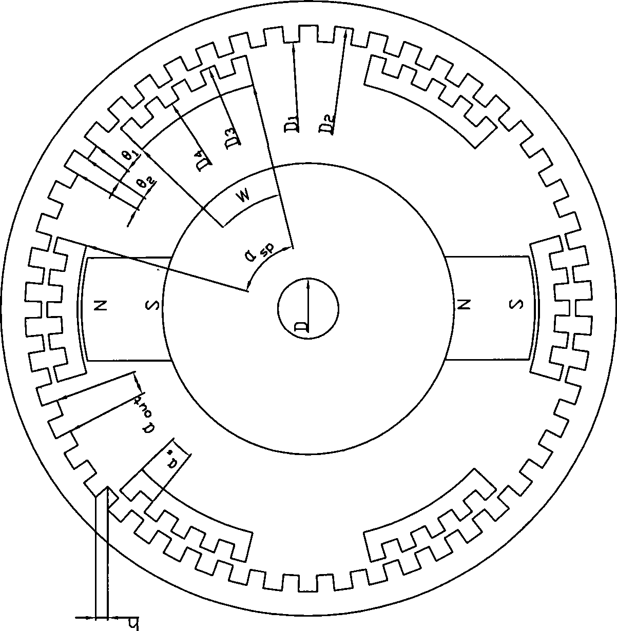
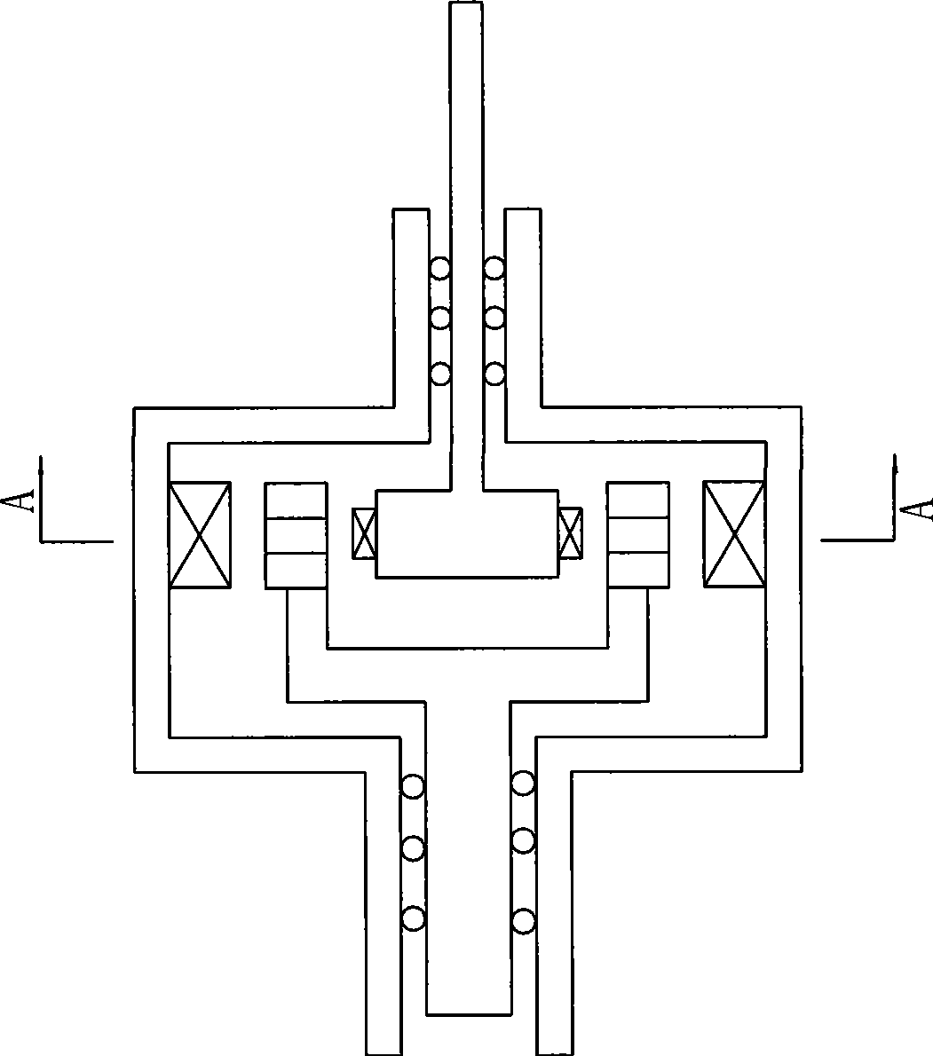
[0028] The so-called gear transmission means that when one gear rotates at one speed, the other gear rotates at a different speed. The invention realizes the change of different rotating speeds based on the theory of the magnetic field. see figure 1 with figure 2 , the inner rotor of the present invention includes magnetic poles made of permanent magnet materials; there are N on the stator t comb teeth; N on the outer rotor sp poles.

[0029] see figure 1 with 2 , this embodiment includes an inner rotor, an outer rotor, and a stator, and the base is radially concentric and embedded, and a non-contact structure is left between the inner rotor and the outer rotor, and the outer rotor and the stator; the inner rotor Located in the inner layer, there is at least one pair of inner rotor poles of permanent magnet material arranged in pairs; ...


PUM


Abstract

The invention relates to the field of electromechanical engineering and concretely discloses a magnetic gear transmission. The magnetic gear transmission comprises an internal rotor, an external rotor and a stator which are sheathed concentrically in the radial direction in an embedding way; a non-contact structure with the clearance is respectively arranged between the internal rotor and the external rotor and between the external rotor and the stator; the internal rotor is positioned on the internal layer and provided with at least one pair of internal rotor magnetic poles which are arranged in pairs and made of permanent magnetic material; the external rotor is positioned on the middle layer and provided with the comb-structured external rotor magnetic poles which are uniformly distributed in pairs and made of ferromagnetic material; the stator is positioned on the external layer, provided with continuous combs and made of ferromagnetic material; and the internal rotor magnetic poles and the external rotor magnetic poles are coplanar with the stator comb. The magnetic gear transmission has the advantages of high efficiency, small noise, easy maintenance, long service life and the like.

Description

technical field [0001] The invention belongs to the field of electromechanical engineering, in particular to a transmission structure of a magnetic gear. Background technique [0002] The existing gear transmissions are basically of the direct contact type with mechanical gear meshing. The disadvantages are low efficiency, high noise, need for lubrication, and easy damage. Especially for occasions requiring large ratios, mechanical gears require multi-stage shifting, which makes the disadvantages of mechanical gear shifting more prominent. Contents of the invention [0003] Aiming at the disadvantages of mechanical gear meshing and direct contact in the prior art, such as low efficiency, high noise, need for lubrication, easy damage, etc., the present invention applies the principle of magnetic field properties, refers to the torque generation characteristics of reluctance motors, and utilizes permanent magnets and ferromagnetic materials. Reasonable combination provides ...

Claims


Application Information

Patent Timeline
Patent Type & Authority Applications(China)
IPC IPC(8): H02K51/00
Inventor 满永奎
Owner 满永奎
Learn More