Slowdown clutch for washing machine

A technology of deceleration clutch and washing machine, applied in the field of washing machine, can solve problems such as bad overrunning clutch, large vibration of washing machine, failure of one-way bearing, etc., and achieve the effects of simple and reliable structure, improved washing ratio, and improved bearing capacity.

Active Publication Date: 2015-07-22
QINGDAO HAIER WASHING MASCH CO LTD
View PDF10 Cites 8 Cited by
  • Summary
  • Abstract
  • Description
  • Claims
  • Application Information

AI Technical Summary

Problems solved by technology

[0006] However, in the washing machine with the above-mentioned deceleration clutch, the inner tub and the pulsator frequently run in opposite directions, and the moment of inertia generated by the inner tub directly acts on the overrunning clutch. quality problem
During the rotation of the inner tub, the one-way bearing will often have a reverse force, and the one-way bearing is prone to failure. At the same time, the clutch spring will be tightened during washing, resulting in damage to the clutch spring; The driving wheel is separated and connected to the reducer. The inner drum swings in the dehydration state, which directly acts on the dehydration shaft. The dehydration shaft is eccentric, causing the washing machine to vibrate and produce noise.

Method used


Image

  • Slowdown clutch for washing machine
  • Slowdown clutch for washing machine
  • Slowdown clutch for washing machine

Examples


Embodiment 1

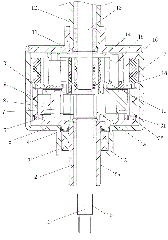
[0039] Such as Figure 1 to Figure 3 As shown, the present invention provides a novel washing machine deceleration clutch, including: input shaft 1, input shaft sleeve 2, rolling bearing 3, oil seal 4, brake wheel 5, speed reducer, connecting shaft 11, dehydration shaft 12, output shaft 13, brake arm 25 and clutch device.

[0040] The input shaft sleeve 2 is flexibly connected with the brake wheel 5 through the cooperation of the rolling bearing 3, and the dehydration shaft 12 is fixedly connected with the brake wheel 5 through the connecting shaft 11 to form a rigid body. The driving wheel 5 and the output shaft 13 are connected with the reducer, the input shaft sleeve 2 is set on the input shaft 1, the dehydration shaft 12 is set on the output shaft 13, and the brake wheel 5 is installed at the journal A of the input shaft sleeve. Two rolling bearings 3 and an oil seal 4, the rolling bearings 3 support the input shaft sleeve 2, and the rolling bearings 3 and the oil seal 4 ...

Embodiment 2

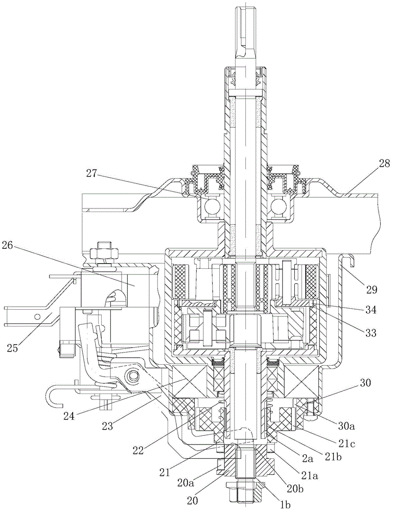
[0045] Such as figure 2 As shown, the clutch control mechanism of the present invention includes a shift fork device 23 and a clutch disc spring 22, the clutch disc spring 22 is sleeved on the outer circle of the input shaft sleeve 2, and abuts against the clutch disc 21, and the shift fork device 23 is hingedly installed On the lower housing 29; the clutch control mechanism synchronously controls the connection / disconnection of the clutch disc 21 and the positioning disc 30 and the disconnection / connection of the clutch disc 21 and the torque transmission sleeve 20 to realize the reverse rotation of the dehydration shaft 12 and the output shaft 13 / The conversion of the same direction of rotation, that is, the conversion of washing and dehydration working conditions.

[0046] The end surface of the torque transmission sleeve 20 close to the clutch disc 21 is provided with a first spline 20a, the inner hole is provided with a first internal spline 20b or a square hole, and t...

Embodiment 3

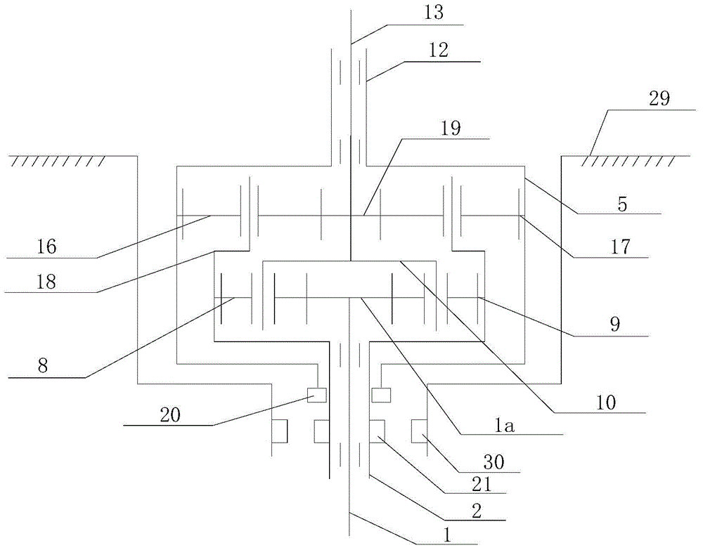
[0051] Such as image 3 As shown, the difference between this embodiment and the second embodiment is that the clutch device is different. The torque transmission sleeve 20 in the clutch device is installed on the end of the brake wheel 5 close to the input shaft 1. According to the torque transmission sleeve 20 The installation position and the structure of the torque transmission bushing 20 are adjusted accordingly. Since the relative positions of the torque transmission bushing 20, the clutch disc 21 and the positioning disc 30 change, the clutch mode also changes correspondingly: when the shift fork device 23 presses down the clutch disc 21 , the clutch disc spring 22 is in a compressed state, and the clutch disc 21 is connected to the torque transmission sleeve 20 and disconnected from the positioning disc 30. At this time, the dehydration shaft 12 and the output shaft 13 rotate in the same direction, that is, they are in the dehydration working condition; When the fork d...


PUM


Abstract

The invention discloses a slowdown clutch for a washing machine. The slowdown clutch comprises an input shaft, an input shaft sleeve, a brake wheel, a speed reducer, a dewatering shaft, an output shaft, a lower shell and a clutch device, wherein the speed reducer is installed in an inner cavity of the brake wheel, the dewatering shaft and the brake wheel are connected into a whole, the input shaft, the input shaft sleeve, the brake wheel and the output shaft are all connected with the speed reducer, the speed reducer is a double-planet gear train composed of a first planet gear train body and a second planet gear train body, the input shaft sleeve and a wheel carrier of the second planet gear train body are connected into a whole, and the input shaft sleeve is movably connected with the brake wheel; the clutch device comprises a positioning disc fixedly installed on the lower shell, a torque transmission shaft sleeve fixedly installed on the input shaft, a clutch disc installed on the input shaft sleeve and capable of being connected with or disconnected from the positioning disc and the torque transmission shaft sleeve, and a clutch control mechanism used for controlling the clutch disc to be connected with or disconnected from the positioning disc and the torque transmission shaft sleeve. The slowdown clutch has the advantages of being simple and compact in structure, low in manufacturing cost, safe and reliable in transmission, efficient, long in service life and low in noise.

Description

technical field [0001] The invention relates to the field of washing machines, in particular to a deceleration clutch for washing machines. Background technique [0002] At present, the function of the deceleration clutch of the pulsator type washing machine is generally to drive the pulsator to reciprocate after decelerating the bidirectional rotation of the motor. The conventional deceleration clutch is mainly composed of an input shaft, an output shaft, an output shaft sleeve, an input shaft sleeve, a brake wheel, a reduction mechanism installed inside the brake wheel, and a clutch component installed on the input shaft sleeve. In washing conditions, the output shaft is required to rotate repeatedly at low speed in both directions. The output shaft sleeve and the brake wheel are integrated. The deceleration mechanism generally only plays a simple deceleration role. When the brake wheel is braked, the output shaft sleeve is also restrained. The two-way rotation of the dri...

Claims


Application Information

Patent Timeline
Patent Type & Authority Applications(China)
IPC IPC(8): D06F37/40F16H3/70F16H57/08F16H57/10F16H57/02F16D11/14
CPCD06F37/40
Inventor 吕佩师杨林张刚金今井俊次
Owner QINGDAO HAIER WASHING MASCH CO LTD
Why Eureka
Try Eureka