Optimizer, photovoltaic power generation system and photovoltaic power generation control method

An optimizer and controller technology, applied in photovoltaic power generation, photovoltaic modules, electrical components, etc., can solve the problems of high communication cost, high communication cost, communication robust power conversion noise and surrounding environmental noise interference, etc., to overcome transmission Effect of short distance and reduction of communication cost

Pending Publication Date: 2018-05-18
深圳古瑞瓦特新能源有限公司
View PDF0 Cites 9 Cited by
  • Summary
  • Abstract
  • Description
  • Claims
  • Application Information

AI Technical Summary

Problems solved by technology

[0002] The distributed photovoltaic power generation system has high requirements for the safety management of the DC side. Usually, the optimizer can be equipped with a Buck / Boost / Buck-Boost DC-DC power conversion circuit, and the inverter can be composed of a step-up DC-DC and an inverter. DC-AC two-stage power conversion structure; in the system, a power carrier (PLC) or wireless (Wireless) communication module can be added between the optimizer and the inverter for communication, that is, the communication mode of weak signal is adopted, and the transmission distance is relatively short , the communication robustness is also susceptible to interference from power conversion noise in the system and surrounding environmental noise, and the use of a dedicated communication module also makes the system have a higher communication cost
Alternatively, the optimizer has a Buck-Boost DC-DC power conversion circuit, and the inverter only uses DC-AC single-stage power conversion; since the function of MPPT and configuration of DC-AC input voltage is realized by the optimizer, the optimizer and the inverter There must be a communication function module that can transmit sampling data and status information between the inverters in real time, so the communication between the optimizer and the inverter must be carried out in a weak signal communication mode of power carrier (PLC) or wireless (Wireless). There are also defects such as short transmission distance, communication robustness easily interfered by power conversion noise in the system and surrounding environment noise, and high communication cost

Method used


Image

  • Optimizer, photovoltaic power generation system and photovoltaic power generation control method
  • Optimizer, photovoltaic power generation system and photovoltaic power generation control method
  • Optimizer, photovoltaic power generation system and photovoltaic power generation control method

Examples


Embodiment 1

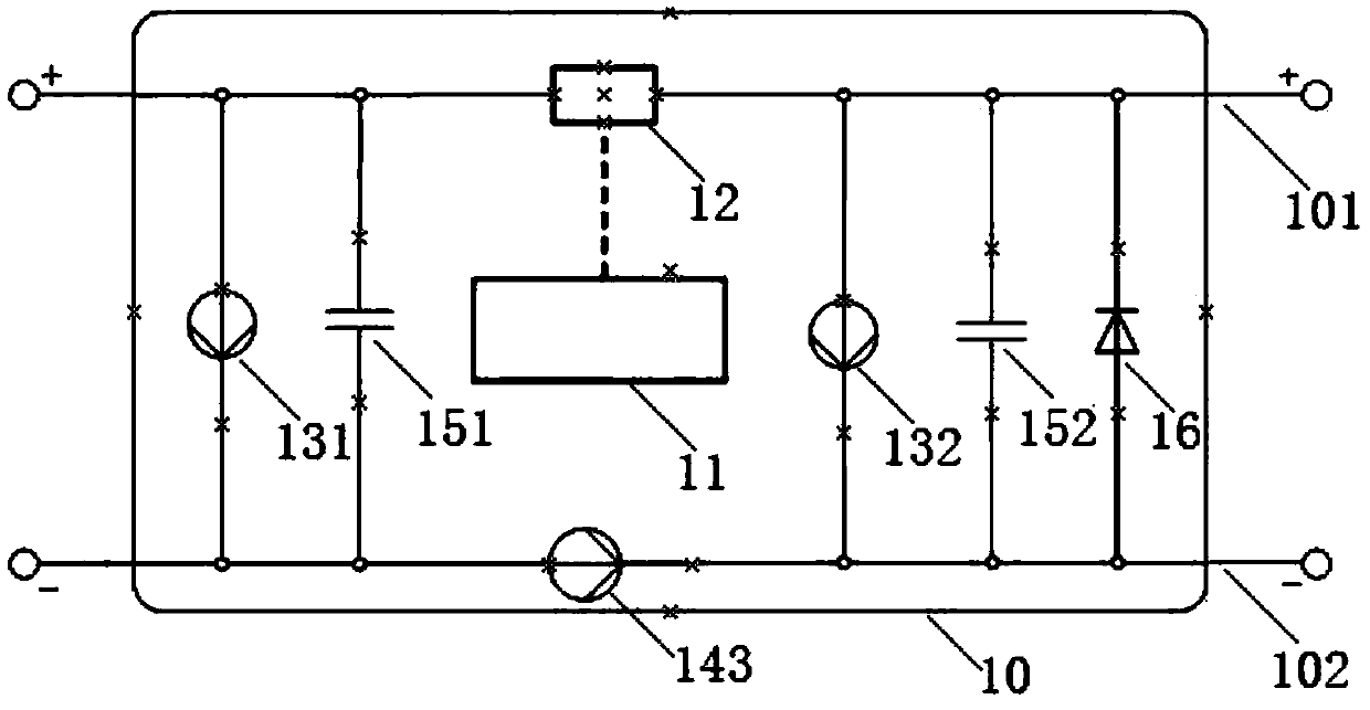
[0023] Such as figure 1 Shown is the optimizer 10 of this embodiment, which includes a positive pole branch 101, a negative pole branch 102, a first voltage sensor 131, a first capacitor 151, a second voltage sensor 132, a second capacitor 152, a bypass diode 16, The optimizer switch 12 (SW_optimizer), the optimizer controller 11 and the third current sensor 143 .

[0024] The optimizer controller 11 is communicatively connected with the optimizer switch 12 , and the communication methods such as wire or wireless can be used. The operating state of the optimizer switch 12 is controlled by the control command issued by the optimizer controller 11 .

[0025] The first voltage sensor 131, the first capacitor 151, the second voltage sensor 132, the second capacitor 152, and the bypass diode 16 are sequentially connected in parallel between the positive branch 101 and the negative branch 101; the optimizer switch 12 is set on the first capacitor 151 On the positive branch 101 betw...

Embodiment 2

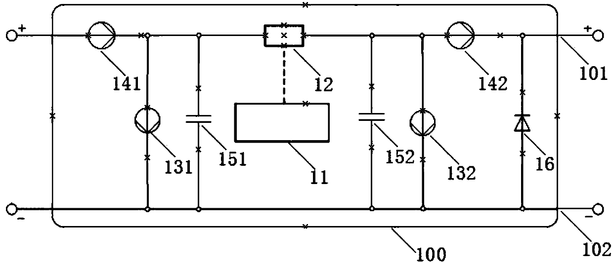
[0031] Such as figure 2 Shown is the optimizer 100 of this embodiment, which includes a positive pole branch 101, a negative pole branch 102, a first voltage sensor 131, a first capacitor 151, a second capacitor 152, a second voltage sensor 132, a bypass diode 16, The optimizer switch 12 , the optimizer controller 11 , and the first current sensor 141 and the second current sensor 142 .

[0032] The optimizer controller 11 is communicatively connected with the optimizer switch 12; a first voltage sensor 131, a first capacitor 151, a second capacitor 152, a second voltage sensor 132, and a bypass are sequentially connected in parallel between the positive branch 101 and the negative branch 102 Diode 16; the first current sensor 141 is arranged on the positive pole input terminal of the optimizer and the positive pole branch 101 of the optimizer switch 12 (specifically, for example, it can be between the positive pole input terminal of the optimizer and the first voltage sensor...

Embodiment 3

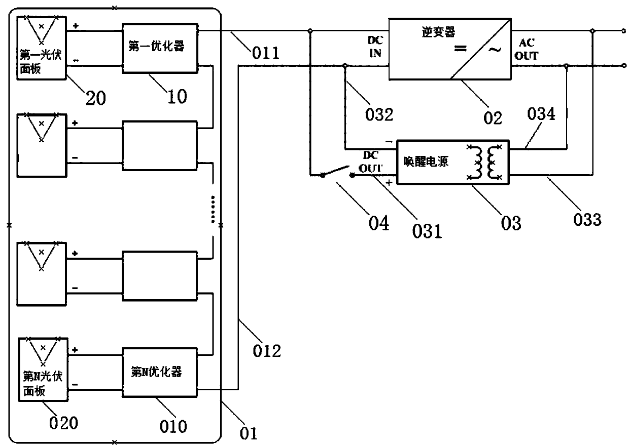
[0035] Such as image 3Shown is the distributed photovoltaic power generation system of this embodiment, which includes a photovoltaic string unit 01, a photovoltaic inverter 02 (Solar / PV Inverter), a wake-up power supply 03 (Start-up Source) and a wake-up switch 04 (SW_start).

[0036] The photovoltaic string unit 01 leads to a positive transmission line 011 and a negative transmission line 012. The positive transmission line 011 and the negative transmission line 012 are introduced from the input end of the inverter 02 and drawn out from the output end of the inverter 02, and then connected to the grid.

[0037] The wake-up power supply 03 is connected in parallel with the inverter 02; the wake-up switch 04 is arranged on the parallel branch of the wake-up power supply 03 and the inverter 02.

[0038] Specifically, the positive power line 031 drawn from the input end of the wake-up power supply 03 is connected to the positive transmission line 011 on the input side of the in...


PUM


Abstract

The application provides an optimizer which includes a positive branch, a negative branch, a first voltage sensor, a first capacitor, a second voltage sensor, a second capacitor, an optimizer switch,an optimizer controller, and a third current sensor or a first current sensor and a second current sensor. The application further provides a photovoltaic power generation system which includes a photovoltaic string unit, an inverter, a wake-up power supply and a wake-up switch. The photovoltaic string unit includes at least one set of photovoltaic panels and the optimizer. The application furtherprovides a photovoltaic power generation control method. The technical scheme of the application overcomes the shortcomings of the prior art: the transmission distance of weak signal communication isshort; the communication robustness is easily affected by the interference from the power transformation noise in the system and the surrounding environment noise; and the communication cost is high.A special weak signal communication module can be omitted. The communication cost of the distributed photovoltaic power generation system can be significantly reduced.

Description

technical field [0001] The invention relates to the field of photovoltaic power generation, in particular to an optimizer, a photovoltaic power generation system and a photovoltaic power generation control method. Background technique [0002] The distributed photovoltaic power generation system has high requirements for the safety management of the DC side. Usually, the optimizer can be equipped with a Buck / Boost / Buck-Boost DC-DC power conversion circuit, and the inverter can be composed of a step-up DC-DC and an inverter. DC-AC two-stage power conversion structure; in the system, a power carrier (PLC) or wireless (Wireless) communication module can be added between the optimizer and the inverter for communication, that is, the communication mode of weak signal is adopted, and the transmission distance is relatively short , the communication robustness is also easily disturbed by the power conversion noise in the system and the noise of the surrounding environment, and the ...

Claims


Application Information

Patent Timeline
Patent Type & Authority Applications(China)
IPC IPC(8): H02S40/30H02J3/38
CPCH02J3/383H02S40/30Y02E10/56
Inventor 骆孝龙丁永强吴良材程浩
Owner 深圳古瑞瓦特新能源有限公司
Why Eureka
Try Eureka