Tunnel configuration method, virtual access node, virtual edge node and system

A virtual access and virtual edge technology, which is applied in transmission systems, digital transmission systems, data exchange through path configuration, etc., can solve problems such as waste of resources and low utilization of tunnels, and achieve normal results

Inactive Publication Date: 2009-08-05
HUAWEI TECH CO LTD
View PDF0 Cites 27 Cited by
  • Summary
  • Abstract
  • Description
  • Claims
  • Application Information

AI Technical Summary

Problems solved by technology

[0012] During the research and practice of the prior art, the inventors found that the prior art has the following problems: At present, PBT is mainly used in the wholesale scene of the access network, and the operator uses the Internet Protocol (Internet Protocol, IP) edge node connected to the Users in the PBT network provide services. As the wholesale tunnel of the access network, the PBT tunnel for the SP to access the PBT network is statically configured by network maintenance personnel. This static configuration leads to low utilization of the tunnel, waste of resources, and When a failure occurs, a new tunnel cannot be established for communication

Method used


Image

  • Tunnel configuration method, virtual access node, virtual edge node and system
  • Tunnel configuration method, virtual access node, virtual edge node and system
  • Tunnel configuration method, virtual access node, virtual edge node and system

Examples


Embodiment 1

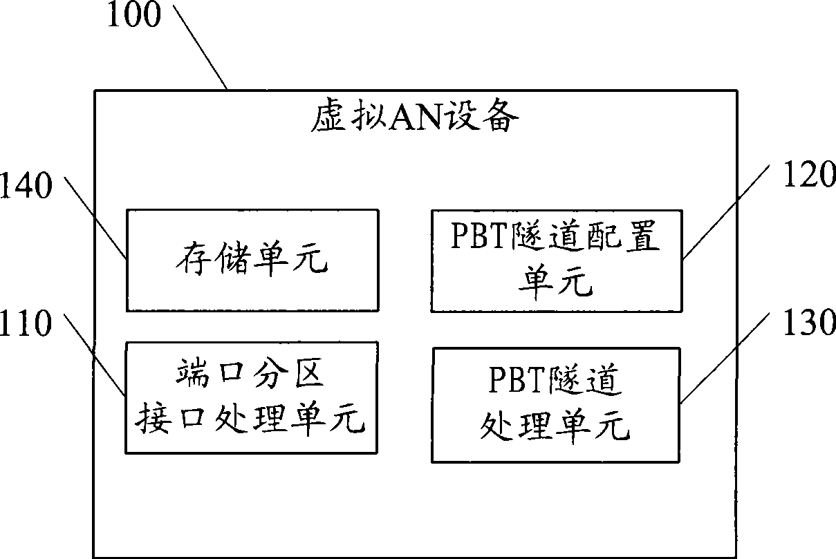
[0055] Embodiment 1, a virtual AN device 100 supporting PBT, the schematic structure is as follows figure 1 As shown, it includes: a port partition interface processing unit 110, a PBT tunnel configuration unit 120, a PBT tunnel processing unit 130 and a storage unit 140;

[0056] The port partition interface processing unit 110 is configured to receive or send data packets from the port corresponding to the virtual MAC address stored in the storage unit;

[0057] The PBT tunnel configuration unit 120 is configured to configure the forwarding table corresponding to the PBT tunnel label between the virtual access node and the edge node through the L2C protocol, where the PBT tunnel label includes: Virtual MAC address, VLAN and the MAC address of the edge node;

[0058] The PBT tunnel configuration unit 120 is further configured to configure, through the L2C protocol, a forwarding table corresponding to the PBT tunnel label between the virtual access node and the virtual edge n...

Embodiment 2

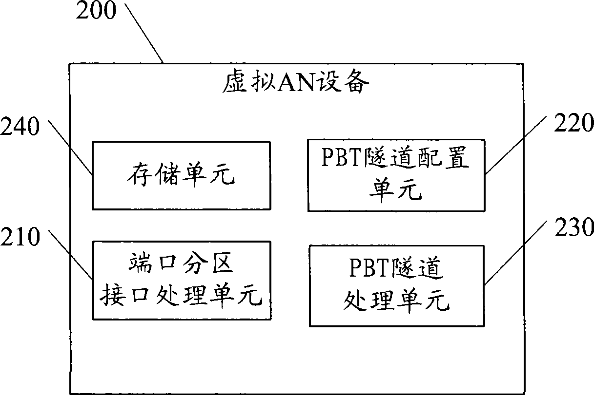
[0062] Embodiment 2, a virtual AN device supporting PBT, the schematic diagram is as follows figure 2 As shown, it includes: a port partition interface processing unit 210, a PBT tunnel configuration unit 220, a PBT tunnel processing unit 230 and a storage unit 240;

[0063] The port partition interface processing unit 210 is configured to receive or send data packets from the port corresponding to the virtual MAC address stored in the storage unit 240;

[0064] The PBT tunnel configuration unit 220 is configured to configure, through the L2C protocol, a forwarding table corresponding to the PBT tunnel label between the virtual access node and the edge node, where the PBT tunnel label includes: Virtual MAC address, VLAN and the MAC address of the edge node;

[0065] The PBT tunnel configuration unit 220 is further configured to configure, through the L2C protocol, a forwarding table corresponding to the PBT tunnel label between the virtual access node and the virtual edge no...

Embodiment 5

[0089] Embodiment 5 is a system for configuring a PBT tunnel. In this embodiment, the technical solution of Embodiment 4 of the present invention is described in detail with reference to specific application examples.

[0090] The structure diagram is as Figure 5 shown, including:

[0091] access node 510 and IP edge node 520;

[0092] The access node 510 includes multiple virtual ANs, virtual AN1˜virtual ANn;

[0093] The IP edge node 520 includes an L2C functional unit 521 ; an edge node PBT tunnel processing unit 522 .

[0094] Each virtual AN consists of a port zone interface processing unit 511 , a PBT tunnel configuration unit 512 and an ANPBT tunnel processing unit 513 .

[0095] The L2C functional unit 521 interacts with the PBT tunnel configuration unit in each virtual AN to establish a PBT tunnel;

[0096] The PBT tunnel is established between the AN PBT tunnel processing unit 513 of each AN and the corresponding edge node PBT tunnel processing unit 522 on the e...


PUM


Abstract

The invention discloses a tunnel configuration method, a virtual access node, a virtual edge node and a system. The tunnel between an IP edge node and a virtual AN is established dynamically, and then the tunnel is provided for an SP network device to realize the control of a port division by the SP network device. The problem of low utilization of the tunnel caused by a PBT tunnel static configuration in the prior art is avoided, and as the tunnel can be allocated dynamically, when a fault occurs in the configuration tunnel, the SP can reapply for a tunnel for service, thus ensuring normal communication.

Description

technical field [0001] The present invention relates to the present invention relates to an operator backbone network transmission technology, in particular to a tunnel configuration method, a virtual access node, a virtual edge node and a system. Background technique [0002] The Provider Backbone Transport (PBT) technology is based on the 802.1ah standard and is improved from the Provider Backbone Bridge (PBB) standard. The goal of PBB technology is to allow Provider Backbone Bridge Networks (PBBNs) under the 802.1ad standard to support up to 2 20 a service VLAN. In addition, PBB also defines the architecture and bridging protocol of PBBN to realize the compatibility and interconnection of multiple PBB networks. [0003] PBB uses MAC address in MAC address encapsulation, that is, the end user Ethernet data frame is re-encapsulated into the carrier Ethernet frame header to form two MAC addresses. In the carrier core network, traffic is forwarded only according to the latt...

Claims


Application Information

Patent Timeline
Patent Type & Authority Applications(China)
IPC IPC(8): H04L12/46H04L12/56H04L45/50
Inventor 郑若滨
Owner HUAWEI TECH CO LTD
Why Eureka
Try Eureka