Resin sealing apparatus

A resin sealing device and resin sealing technology, applied in electrical components, household components, household appliances, etc., can solve problems such as hindering shortening of work cycle, standby, etc., and achieve the effect of preventing poor gate removal and improving cooling efficiency

Active Publication Date: 2011-03-16
TOWA
View PDF1 Cites 0 Cited by
  • Summary
  • Abstract
  • Description
  • Claims
  • Application Information

AI Technical Summary

Problems solved by technology

[0007] However, in such a structure, the molded product cannot be cooled until immediately before the gate removal process, and although the molded product is already placed at a position where the gate can be removed, it takes a corresponding amount of time to stand by until it is sufficiently cooled.
This cooling time (standby time of the gate removal unit) directly affects the operation cycle of the device, so it is the main factor hindering the shortening of the operation cycle

Method used


Image

  • Resin sealing apparatus
  • Resin sealing apparatus
  • Resin sealing apparatus

Examples


Embodiment Construction

[0030] Hereinafter, an example of an embodiment of the present invention will be described in detail with reference to the drawings.

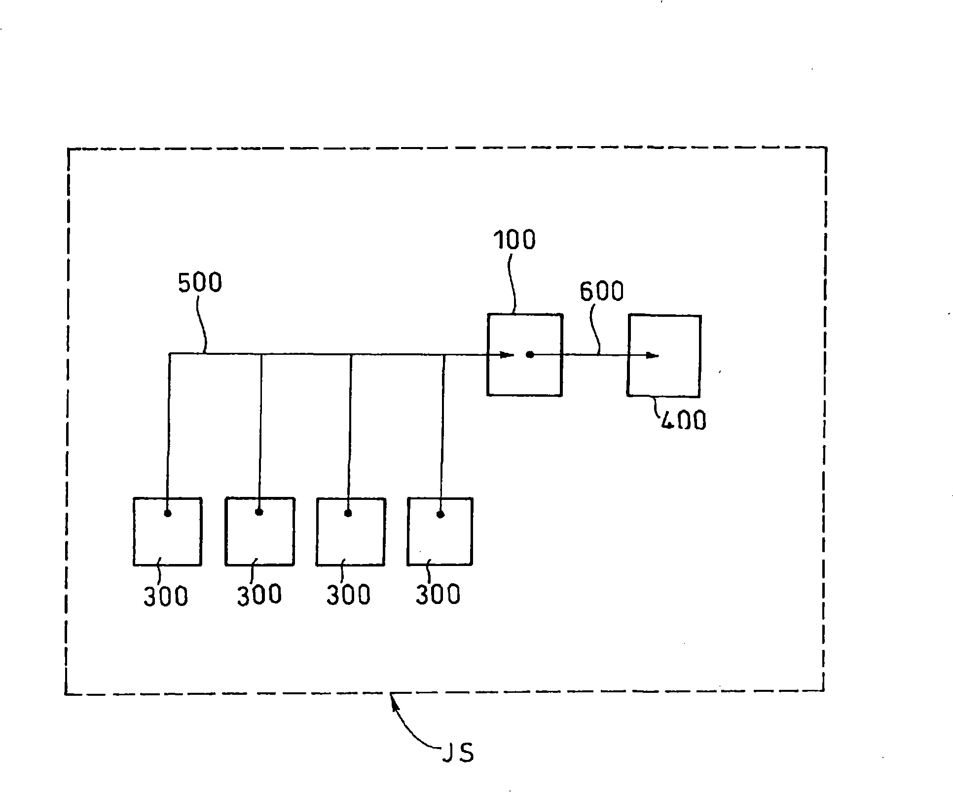
[0031] The resin sealing device JS related to the present invention is as figure 1 As shown in its schematic structure, it has the following structure: sealing unit 300, which seals molded products such as semiconductor chips with resin; cooling unit 100, which cools molded products sealed with resin by sealing unit 300; gate removal unit 400 , removing unnecessary resin from the molded product cooled by the cooling unit 100 ; In addition, the resin sealing device JS is a so-called multi-press type resin sealing device in which a plurality of sealing units 300 are arranged in parallel for one gate removal unit 400 . Moreover, in the resin sealing apparatus JS, the molded product is conveyed from each sealing unit 300 to the cooling unit 100 by the first conveyance unit 500 , and the conveyance from the cooling unit 100 to the gate removal uni...


PUM


Abstract

A resin sealing apparatus that realizes accurate gate break while ensuring a shortening of cycle time of resin sealing apparatus through attaining of entry of a molded item after satisfactory cooling into a gate break operation. The resin sealing apparatus comprises sealing means (300) for sealing a molded item, such as semiconductor chip, with a resin, and gate break means (400) for removing anyunwanted resin from the molded item having undergone the resin sealing by the sealing means (300), and further comprises cooling means (100) for cooling the molded item before the gate break thereof,and delivery means (600) for delivering the molded item after cooling from the cooling means (100) to the gate break means (400).

Description

technical field [0001] The present invention relates to the technical field of resin sealing devices for sealing semiconductor products with resin. Background technique [0002] In the past, publicly Figure 9 The described semiconductor molding apparatus (resin sealing apparatus) 1 (refer to Japanese Unexamined Patent Publication No. 7-58137). [0003] The semiconductor molding apparatus 1 is configured as follows: a molding device 11 for resin molding a semiconductor chip; a take-out unit 25 for taking out a workpiece 19 formed by resin molding by the molding device 11 from the molding device 11; 27, receiving the workpiece (formed product) 19 taken out from the taking-out unit 25; cooling unit 31, cooling the workpiece 19 received by the support body 27; pressing unit (gate break unit (gate break)) 30, removing the workpiece 19 Press between the pressing unit 30 and the above-mentioned support body 27, and cooperate with the support body 27 to fold the gate from the work...

Claims


Application Information

Patent Timeline
Patent Type & Authority Patents(China)
IPC IPC(8): H01L21/56B29C45/14B29C45/17B29L31/34
CPCB29C45/7207B29C45/14655H01L21/67126B29C45/382B29C45/14B29C45/17B29L2031/34H01L21/56
Inventor 泽田博行
Owner TOWA
Why Eureka
Try Eureka