
Device for expanding and fusing bone

A fusion device and bone grafting technology, applied in the direction of internal bone synthesis, fixator, internal fixator, etc., can solve the problems of adjacent vertebral fractures, cannot completely replace PMMA, and is not biodegradable

Inactive Publication Date: 2012-01-25
梁淑君 +1
View PDF1 Cites 0 Cited by
  • Summary
  • Abstract
  • Description
  • Claims
  • Application Information

AI Technical Summary

Problems solved by technology

[0007] 2. The coagulation process can cause hypotension or vascular embolism
[0009] 4. The mechanical strength of the vertebral body after PMMA injection is different from that of the adjacent uninjected vertebral body, and the fracture of the adjacent vertebral body is easily caused by stress concentration
[0010] 5. PMMA releases some toxic monomers
[0012] 7. PMMA has no bone conduction effect, is not biodegradable, and cannot be replaced by autologous bone in the end
[0013] In view of the shortcomings of bone cement PMMA, many scholars have studied a variety of methods, such as using polyester mesh, absorbable balloons, etc. to wrap PMMA bone cement, using injectable artificial bones such as calcium sulfate, calcium phosphate, hydroxyapatite, Chitin, etc. replace PMMA, etc., but all have problems of one kind or another, and still cannot completely replace PMMA

Method used


Image

  • Device for expanding and fusing bone
  • Device for expanding and fusing bone
  • Device for expanding and fusing bone

Examples

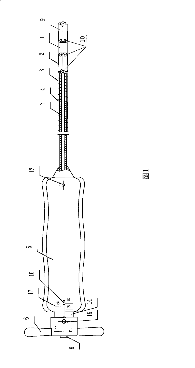
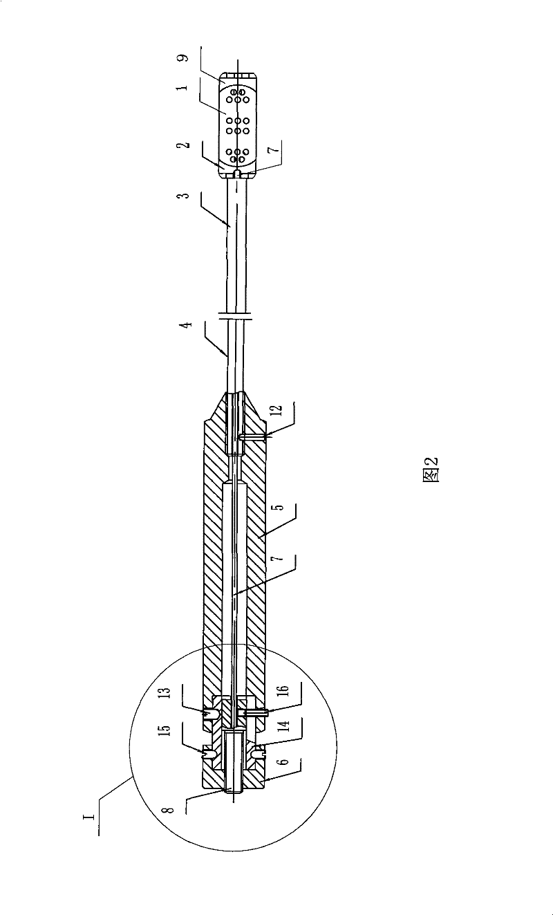
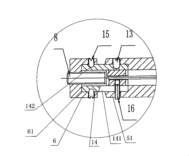

Embodiment Construction

[0030] For ease of understanding, the figure 1 , 2 The right side is called the distal or front end, and the left side is called the proximal or back end.

[0031] Now refer to the attached Figure 1~4 , describe in detail the specific implementation of the bone expansion fusion device of the present invention, the structure of the bone expansion fusion device of the present invention has a head 1, a neck 2, a waist 3, a connecting tube 4, a handle 5 and a handle 6; the head 1 and the neck 2 and between the proximal ends of the two necks are hinged to form a whole, the head 1, the neck 2, the waist 3, the connecting pipe 4, and the handle 5 are all hollow bodies, and a pull rod 7 Through the hollow body, the handle 6 is connected to a tension bolt 8, the tension bolt 8 is connected to one end of the pull rod 7, and there are struts 9 on both sides of the other end of the pull rod 7, so The two ends of the strut 9 are respectively movably connected with the pull rod 7 and th...


PUM


Abstract

A bone expansion fusion cage relates to a fixed apparatus in minimal invasion surgery, which mainly treats cancellous bone fracture and comprises a head, a neck, a waist, a connector pipe, a handle and a swing handle; wherein, the head, neck, waist, connector pipe and handle are hollow and the hollow body is internally provided with tension rods; a central tension bolt of the swing handle is connected with the tension rods; the tension rods are provided with locking pins; both sides of the front end of the tension rod are provided brace rods; both ends of the brace rod are movably connected with the tension rod and the head; the far end of the waist props against but is not connected with the near end of the neck; the swing handle is movably connected with a handle pad at the near end of the handle; the head employs different shapes of appearance; the neck and the brace rod are respectively of two diamond shapes; the head and the brace rod are provided with a plurality of bone graft windows; the neck is provided with a bone graft window; the fusion cage is completely folded; the far ends of the tension rods are wholly housed in the head, the neck and the groove at the inner side of the brace rod and are completely strutted; the head and two necks as well as the head and two brace rods are all fixed into right angles; straight lines are formed between the two necks and the two brace rods by fixation, at the moment, the head forms a cuboid with the two necks and the inner sides of the two brace rods.

Description

technical field [0001] The invention relates to an internal fixation device for minimally invasive medical spinal surgery, in particular to a bone expansion fusion device, which is mainly used for treating osteoporotic vertebral body compression fractures, and can also be used for treating fractures and partial fractures of cancellous bones in other parts. Traumatic or certain pathological vertebral compression fractures, etc. Background technique [0002] Osteoporosis is a common disease that threatens the health of the elderly. Spinal compression fracture is one of the important complications of osteoporosis, which greatly increases the morbidity and mortality of the elderly. At present, there are two main minimally invasive surgical methods for the treatment of osteoporotic vertebral fractures: [0003] 1. In 1984, Deramond of France first applied percutaneous intravertebral injection of bone cement (polymethylmethacrylate), referred to as PMMA, called percutaneous vert...

Claims


Application Information

Patent Timeline
Patent Type & Authority Patents(China)
IPC IPC(8): A61B17/70A61F2/44
Inventor 吴乃庆
Owner 梁淑君
Learn More