Material dynamic double-pressing and shearing experimental device based on Hopkinson rod

An experimental device and dynamic technology, applied in the direction of using stable shear force to test the strength of materials, measuring devices, analyzing materials, etc. problem, to achieve the effect of simple operation and small footprint

Active Publication Date: 2009-08-12
NORTHWESTERN POLYTECHNICAL UNIV
View PDF0 Cites 36 Cited by
  • Summary
  • Abstract
  • Description
  • Claims
  • Application Information

AI Technical Summary

Problems solved by technology

[0008] In order to overcome the complexities of the experimental system in the prior art, the large footprint, the complex shape of the sample, the difficulty in processing, the unsatisfactory stress s

Method used


Image

  • Material dynamic double-pressing and shearing experimental device based on Hopkinson rod
  • Material dynamic double-pressing and shearing experimental device based on Hopkinson rod
  • Material dynamic double-pressing and shearing experimental device based on Hopkinson rod

Examples


Embodiment 1

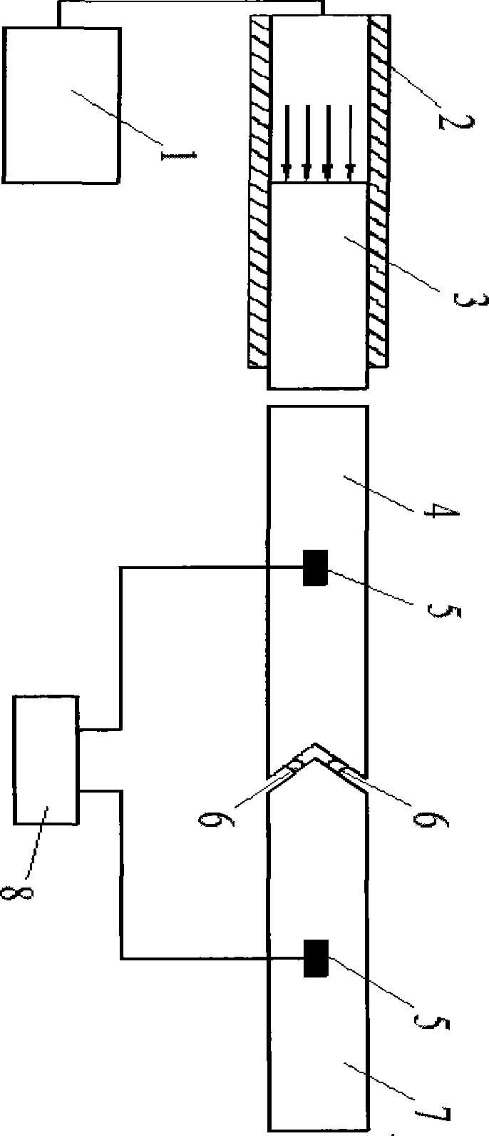
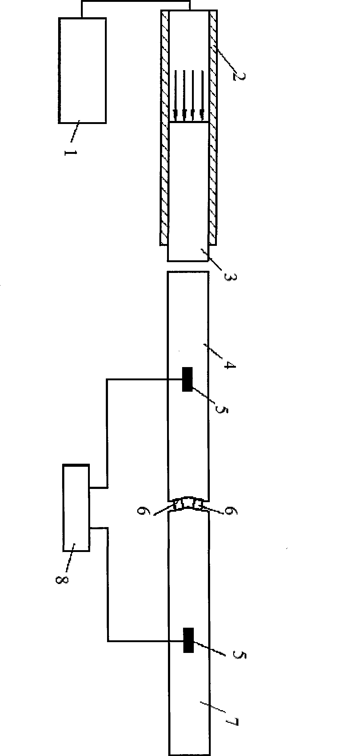
[0021] Such as figure 1 As shown: this embodiment includes a striking rod 3 , an incident rod 4 , a transmission rod 7 , two identical samples 6 , a striking rod launching mechanism 2 and a high-pressure air source 1 . In this embodiment, the end of the incident rod 4 adjacent to the transmission rod 7 is processed into a V-shaped groove, and the end of the matching transmission rod 7 is a wedge-shaped head, and the V-shaped groove of the incident rod 4 and the transmission rod 7. The included angle between the inclined plane of the wedge-shaped head and the axis of the bar is 60°. One end of the incident rod 4 with a V-shaped groove and one end of the wedge-shaped head of the transmission rod 7 are installed coaxially opposite each other, and the two samples 6 are sandwiched between the two slopes. The other end of the incident rod is provided with a striking rod 3, a striking rod launching mechanism 2 and a high-pressure air source 1. In addition, there is a data acquisiti...

Embodiment 2

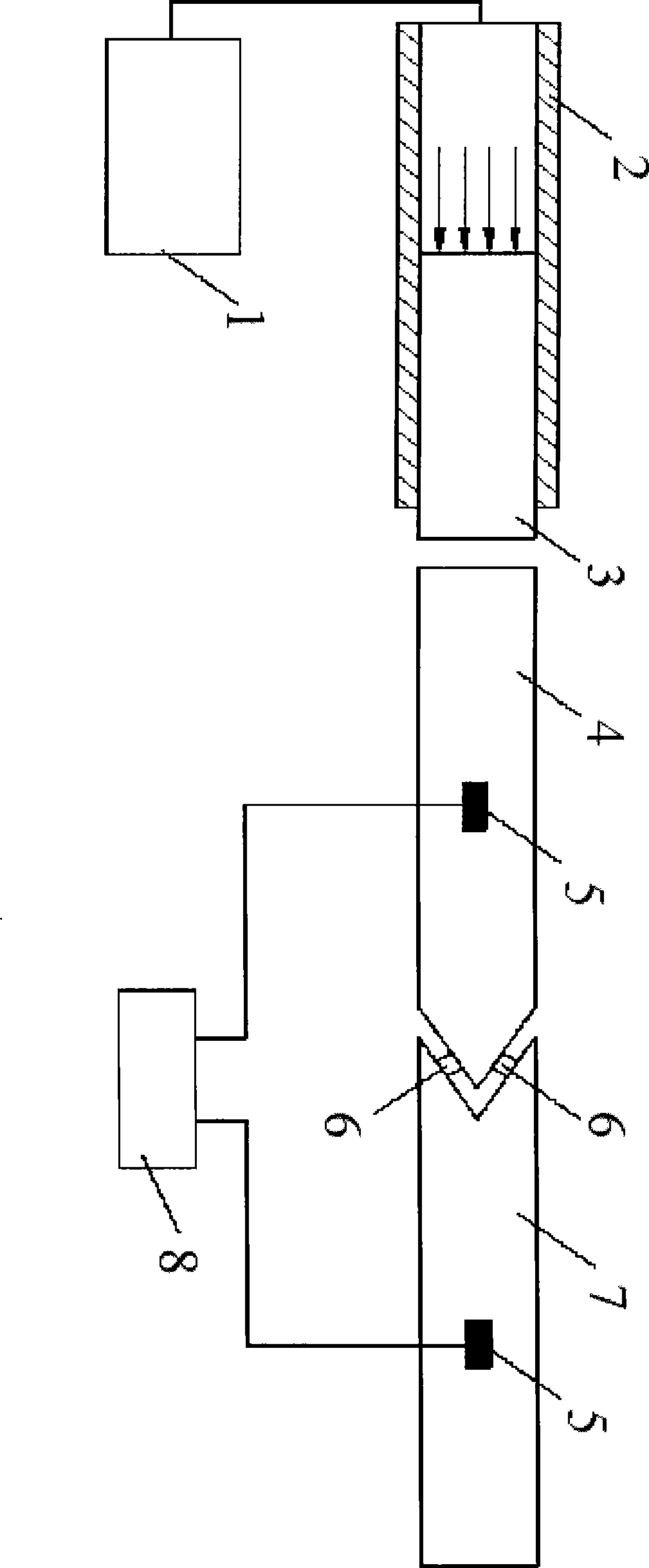
[0030] Such as figure 2 As shown: this embodiment includes a striking rod 3 , an incident rod 4 , a transmission rod 7 , two identical samples 6 , a striking rod launching mechanism 2 and a high-pressure air source 1 . In this embodiment, the difference from Embodiment 1 is that the end of the incident rod 4 in contact with the sample is processed into a wedge-shaped head, and the end of the transmission rod 7 in contact with the sample is processed into a V-shaped groove. The included angle between the slope of the wedge-shaped head and the V-shaped groove of the transmission rod 7 and the axis of the rod is 30°. One end of the wedge-shaped head of the incident rod 4 and one end of the V-shaped groove of the transmission rod 7 are installed coaxially opposite each other, and the two samples 6 are respectively sandwiched between the two inclined surfaces. The other end of the incident rod is provided with a striking rod 3, a striking rod launching mechanism 2 and a high-pres...

Embodiment 3

[0039] Such as figure 1 As shown: this embodiment includes a striking rod 3 , an incident rod 4 , a transmission rod 7 , two identical samples 6 , a striking rod launching mechanism 2 and a high-pressure air source 1 . In this embodiment, the end of the incident rod 4 adjacent to the transmission rod 7 is processed into a V-shaped groove, and the end of the matched transmission rod 7 is a wedge-shaped head, and the V-shaped groove of the incident rod 4 and the transmission rod 7. The included angle between the inclined plane of the wedge-shaped head and the axis of the rod is 80°. One end of the incident rod 4 with a V-shaped groove and one end of the wedge-shaped head of the transmission rod 7 are installed coaxially opposite each other, and the two samples 6 are sandwiched between the two slopes. The other end of the incident rod is provided with a striking rod 3, a striking rod launching mechanism 2 and a high-pressure air source 1. In addition, there is a data acquisitio...


PUM


Abstract

The invention relates to a double compression shear experimental device for material dynamics based on a Hopkinson rod. The experimental device comprises a strain foil (5), an impact rod (3), an incident rod (4) and a transmission rod (7); the experimental device is characterized in that one of the adjacent ends of the incident rod (4) and the transmission rod (7) is a V-shaped groove or a wedgy head, while the other end is a wedgy head or a V-shaped groove; included angles between the bevels of the V-shaped groove and the wedgy head and the axes of the incident rod (4) and the transmission rod (7) are the same and between 30 and 80 degrees; and two test samples are symmetrically clamped between the bevels of the V-shaped groove and the wedgy head. The experimental device does not need to make large change to the Hopkinson pressure rod, only needs to reprocess one incident rod (4) of which one end is provided with the wedgy head or the V-shaped groove and a pressure rod of which one end is provided with the V-shaped or the wedgy head and adopts a test sample of the conventional Hopkinson pressure rod to simultaneously apply the impact load combining compression shear on two test samples. The experimental device has the characteristics that equipment has small occupied area, attractive appearance, elegance and simple operation.

Description

1. Technical field: [0001] The invention relates to a testing device for dynamic mechanical properties of materials, in particular to a dynamic double-compression-shearing experimental device for materials based on Hopkinson rods. 2. Background technology: [0002] In practical applications, the mechanical properties and failure process of materials are generally in a complex stress state, that is, they are subjected to normal and tangential forces at the same time, and the tangential force often plays a very important role in the destruction of materials. effect. Therefore, understanding the mechanical response characteristics of materials under combined compression-shear loading has become a research hotspot in related fields. [0003] At present, in terms of dynamic compression-shear experiment techniques, there are currently three main categories: [0004] The first type is the slant plate impact experiment. This technology uses air cannons to carry out parallel impact...

Claims


Application Information

Patent Timeline
IPC IPC(8): G01N3/307G01N3/24
Inventor 李玉龙索涛史娇红郭伟国
Owner NORTHWESTERN POLYTECHNICAL UNIV
Why Eureka
Try Eureka