
Bearing and spindle motor

A technology for spindle motors and bearings, applied in the field of spindle motors and bearings, can solve problems such as unevenness and unreliable optical reading devices, and achieve the effect of reducing axial vibration

Inactive Publication Date: 2009-08-12
LG INNOTEK CO LTD
View PDF0 Cites 9 Cited by
  • Summary
  • Abstract
  • Description
  • Claims
  • Application Information

AI Technical Summary

Problems solved by technology

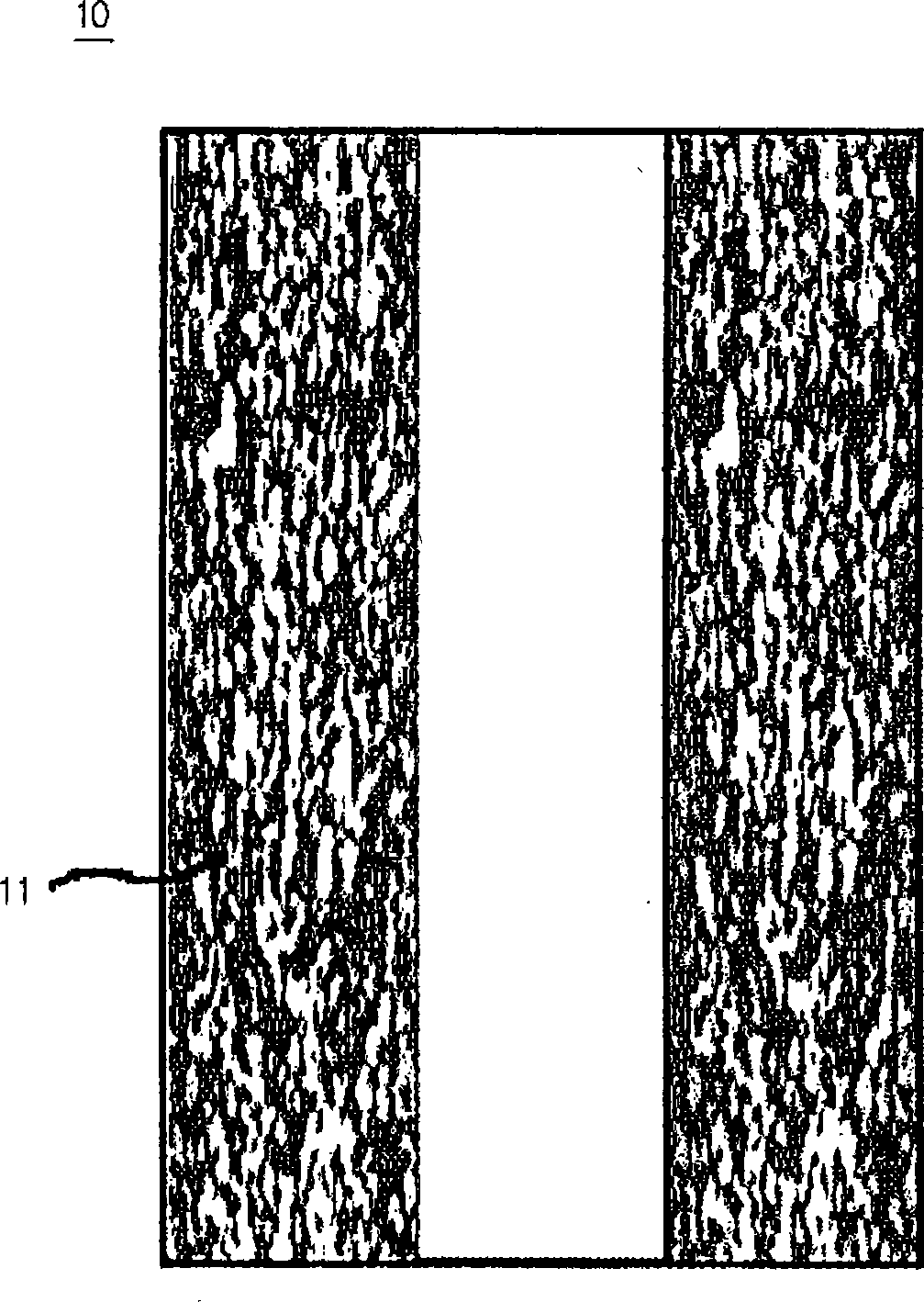
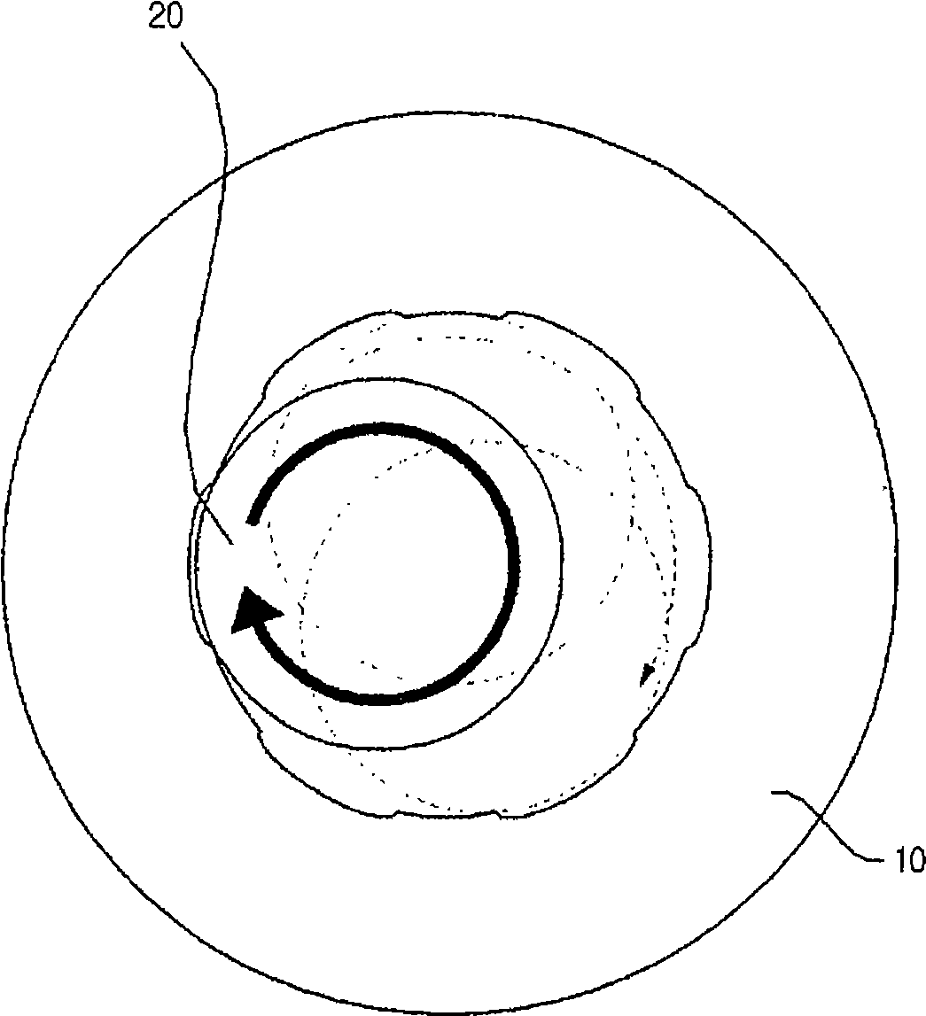
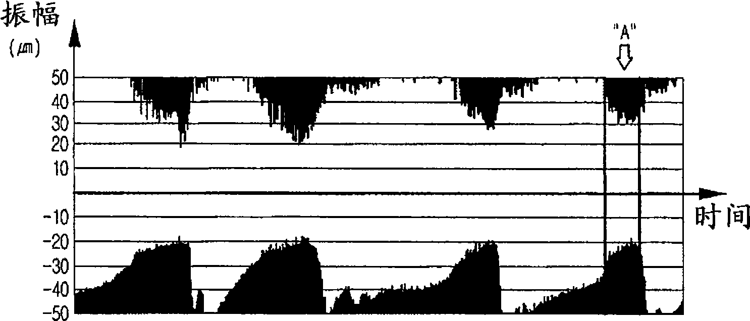
Thus, a disadvantage of the spindle motor comprising the bearing 10 is that when the shaft 20 rotates in the bearing 10, the shaft 20 vibrates in the radial direction because the inner surface of the bearing 10 is uneven due to the presence of the hole 11
Therefore, optical reading devices using spindle motors are not very reliable

Method used


Image

  • Bearing and spindle motor
  • Bearing and spindle motor
  • Bearing and spindle motor

Examples


Embodiment Construction

[0037] The accompanying drawings illustrate examples of embodiments of the invention, and the following description will refer to these embodiments in detail.

[0038] Figure 5 is a sectional view showing the spindle motor according to the embodiment.

[0039] refer to Figure 5 , the bearing seat 120 is installed on the base 110 . The bearing 130 is tightly fitted in the bearing housing 120 to support the lower portion of the rotatable shaft 140 . The bearing 130 is formed by sintering metal powder. Thus, the bearing 130 can include holes 131 on its surface and in its interior for receiving oil (cf. Figure 6 ).

[0040] The stator 150 is fixed to the bearing housing 120 and the rotor 160 is fixed to the shaft 140 . The stator 150 includes a core 151 and a coil 155 . The core 151 is fixed to the outer surface of the bearing housing 120 , and the coil 155 is wound around the core 151 . The rotor 160 includes a rotor yoke 161 and magnets 165 . The rotor yoke 161 is fi...


PUM


Abstract

Provided is a sintered bearing with oil for a spindle motor. The bearing is characterized in that at least one portion of upper and lower sides of the bearing is denser than other portions of the bearing.

Description

technical field [0001] The invention relates to a bearing and a spindle motor including the bearing. Background technique [0002] The spindle motor is used in an optical disc drive (ODD) for rotating the disc while moving the optical pickup device in the radial direction of the disc to read data from the disc. In an optical disc drive, a disc is loaded on a turntable fixed to a shaft. Thus, the disk can be rotated by driving the turntable. The shaft is supported by bearings that fit tightly into the housings. [0003] figure 1 is a sectional view showing the bore of a bearing 10 according to the prior art, figure 2 is a plan view showing the bearing 10 and the shaft 20 coupled to the bearing 10 . [0004] refer to figure 1 , The bearing 10 is formed from sintered metal powder. After the bearing 10 is cut longitudinally, when a cross-sectional image of the bearing 10 is obtained by using a scanning electron microscope, holes 11 can be found in the bearing 10 as well ...

Claims


Application Information

Patent Timeline
Patent Type & Authority Applications(China)
IPC IPC(8): H02K7/08
CPCG11B19/2009F16C2370/12F16C33/103H02K7/085H02K5/16H02K7/08
Inventor 宋忠炫李泰旭
Owner LG INNOTEK CO LTD
Learn More