Broadband impedance matching circuit using high pass and low pass filter sections

A technology of impedance matching circuit and low-pass filter, which is applied in the direction of impedance matching network, amplifier input/output impedance improvement, impedance network, etc., which can solve the problems of complex design of impedance matching circuit and increased return loss reflection

Inactive Publication Date: 2009-08-12
HARRIS CORP
View PDF3 Cites 4 Cited by
  • Summary
  • Abstract
  • Description
  • Claims
  • Application Information

AI Technical Summary

Problems solved by technology

[0008] Unfortunately, the aforementioned prior art impedance matching circuits are complex in design and require many components, which add considerably to the return loss reflection

Method used


Image

  • Broadband impedance matching circuit using high pass and low pass filter sections
  • Broadband impedance matching circuit using high pass and low pass filter sections
  • Broadband impedance matching circuit using high pass and low pass filter sections

Examples


Embodiment Construction

[0018] Like reference characters designate like parts throughout the several views of the drawings.

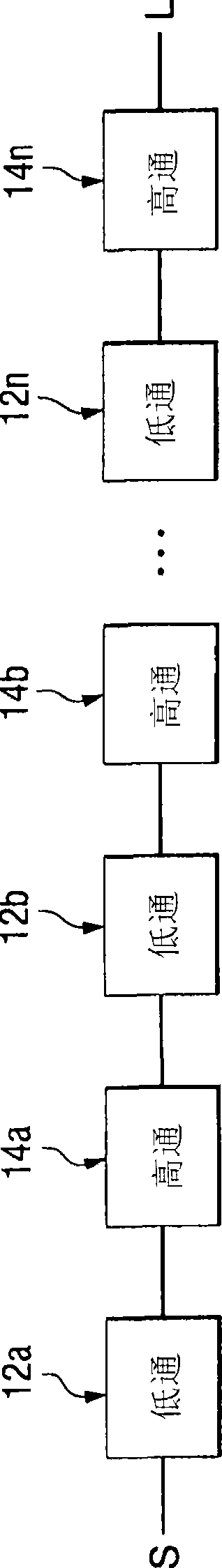
[0019] Referring to FIG. 2, a preferred embodiment of a broadband impedance matching circuit 10 includes a plurality of low-pass filters 12 and a plurality of high-pass filters 14, which are cascaded together alternately between a power source S whose impedance will be equal to The impedance of the load L is matched. Alternating cascaded sequences can start or end with a low-pass filter or a high-pass filter ( Figure 2A shows a sequence starting with a low-pass segment followed by a high-pass segment, while Figure 2B A sequence starting with a high-pass segment followed by a low-pass segment is shown).

[0020] More specifically, in Figure 2A In , the output of the first low-pass filter 12a is connected to the input of the first high-pass filter 12b. Next, the output of the first high-pass filter 12a is connected to the input of the second low-pass filter 12b, and the o...


PUM


Abstract

A broadband impedance matching circuit using high pass and low pass filter sections alternatingly cascaded together to yield considerably broader band matching than two high pass sections or two low pass filter sections. By alternating the high pass filter sections with the low pass filter sections, significantly fewer elements are required for a given result than non-alternating prior art cascaded filter sections. Consequently, the alternating filter sections according to the present invention significantly improves the return loss at increased bandwidths.

Description

technical field [0001] The present invention relates to impedance matching. More specifically, the present invention relates to broadband impedance matching using high-pass and low-pass filters. Background technique [0002] Maximum power transfer from a source to its load occurs when the load impedance is equal to the complex conjugate of the source impedance. More specifically, when the load impedance is equal to the complex conjugate of the source impedance, any source reactance resonates with an equal but opposite load reactance, leaving only equal resistance values ​​of the source and load reactances. Therefore, maximum power is transferred from the source to the load because the source resistance is equal to the load resistance. [0003] The simplest matching circuit for matching two real impedances is a network consisting of two elements (an inductor and a capacitor) connected in an "L" network. When the shunt element is a capacitor, the L-network acts as a low pas...

Claims


Application Information

Patent Timeline
Patent Type & Authority Applications(China)
IPC IPC(8): H03H7/38H03H11/28
CPCH03H11/28H03F1/56H03F2200/387H03H7/38
Inventor 罗伯特·D·塔尔博特
Owner HARRIS CORP
Why Eureka
Try Eureka