
Vehicle intelligent device capable of automatically recognizing road speed-limit sign

A speed limit sign and automatic recognition technology, applied in the field of vehicle intelligence, can solve the problems of actual vehicle positioning error, difficult sensing signal accuracy, and affecting vehicle accuracy

Inactive Publication Date: 2009-08-19
SHANGHAI JIAO TONG UNIV
View PDF2 Cites 34 Cited by
  • Summary
  • Abstract
  • Description
  • Claims
  • Application Information

AI Technical Summary

Problems solved by technology

The disadvantage of this patent is that: "iron barcodes must be set on the road surface", the investment in road construction is large, and maintenance is difficult; This technology relies on the magnetic coil sensor "set under the chassis of the car close to the road" to realize the signal detection of "iron barcodes on the road", which is difficult to ensure the accuracy of the sensing signal
The technical disadvantage of this patent is that it must "rely on satellite positioning technology or mobile phone communication network positioning technology" and "information stored in the controller", and "information update" must be "realized through the communication network"; The limitation of the accuracy of civil satellite positioning technology and mobile phone communication network positioning technology will cause large errors in the actual positioning of vehicles, which will affect the accuracy of vehicle overspeed alarm and assisted driving control

Method used


Image

  • Vehicle intelligent device capable of automatically recognizing road speed-limit sign
  • Vehicle intelligent device capable of automatically recognizing road speed-limit sign
  • Vehicle intelligent device capable of automatically recognizing road speed-limit sign

Examples


Embodiment

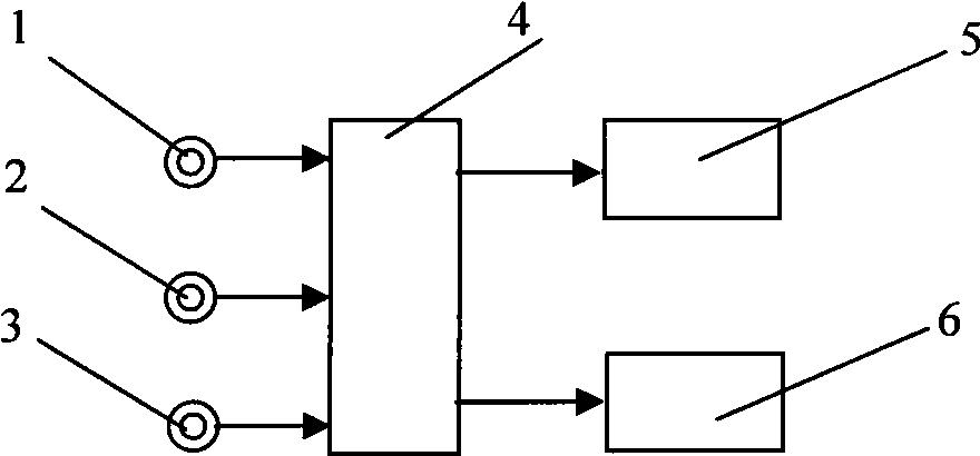
[0038] After the vehicle is started, the device of this embodiment enters the working state;

[0039] The three pinhole cameras installed on the vehicle collect scene images in three directions in front of the vehicle at the same time; the three pinhole cameras respectively transmit the analog signals of the road speed limit sign images collected by their respective output interfaces to the signal via video cables. processor;

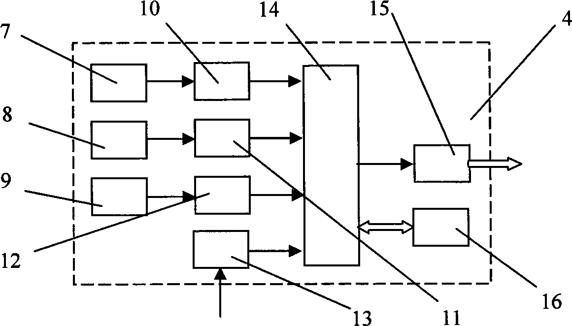
[0040] The signal processor processes the three images collected by the three pinhole cameras in real time, recognizes the speed limit sign of the vehicle on the current road section on the image, and outputs the control command through the output interface of the speed limit recognition result;

[0041] The control command is sent to the vehicle speed control mechanism through the output interface of the signal processor. Once the current vehicle speed is greater than the speed limit identification value, the vehicle speed control mechanism can reduce ...


PUM


Abstract

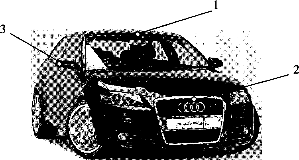
The invention relates to a vehicle intelligent device for automatically identifying road speed limit signs in the technical field of vehicle intellectualization. The vehicle intelligent device comprises three pinhole cameras, a single processor, a vehicle speed control mechanism and a speech prompter, wherein the first pinhole camera is arranged in a right central position of the upper edge of a vehicle front view glass frame, and is used for acquiring vehicle speed limit sign images which are arranged on the front upper side of a road; the second pinhole camera is arranged in the right central position of a front cover of a vehicle motor, and is used for acquiring the speed limit sign images on the road in the front of the vehicle; the third pinhole camera is arranged in a position of a right back view mirror cover near the right edge, and is used for acquiring the speed limit sign images on the right side of the road; and the signal processor processes the images which are acquired by the three pinhole cameras in real time, identifies the speed limit signs of a current road section to the running of the vehicle, and outputs control instructions according to a speed limit identification result so as to automatically control the speed of the vehicle. At the same time, drivers can know road speed limit information in real time, and cannot cause the vehicle to be overspeed because of temporary neglect.

Description

technical field [0001] The invention relates to a device in the technical field of vehicle intelligence, in particular to a vehicle intelligent device for automatically recognizing road speed limit signs. Background technique [0002] For the safety of roads and vehicles, urban roads and high-grade highways, especially expressways, must set vehicle speed limit signs on each road section, so as to remind vehicle drivers to control the speed and drive carefully, so as to avoid illegal or even traffic accidents due to speeding. cause a traffic accident. However, when there are few vehicles in front, vehicle drivers tend to neglect their own driving speed, and speeding occurs. Although with the advancement of science and technology, many roads have been installed with vehicle speed monitoring devices, but judging from their effects, they are basically punitive technical means and measures, warning drivers to obey traffic regulations through punitive means, now Some road speed ...

Claims


Application Information

Patent Timeline
IPC IPC(8): B60W40/00B60W30/14B60W40/06B60R11/04G06K9/00
Inventor 张秀彬徐林程远钱斐婓
Owner SHANGHAI JIAO TONG UNIV
Learn More