Suspension conveyance apparatus

A handling device and suspended technology, applied in the directions of transportation and packaging, unpowered systems, railway car body parts, etc., can solve the problems of inability to reliably prevent lateral movement, difficult to support tools for objects to be transported, and high overall equipment costs. The effect of easy implementation, easy configuration, simple configuration

Inactive Publication Date: 2009-08-19
DAIFUKU CO LTD
View PDF1 Cites 11 Cited by
  • Summary
  • Abstract
  • Description
  • Claims
  • Application Information

AI Technical Summary

Problems solved by technology

[0003] However, when using the anti-swing mechanism of the above-mentioned conventional structure, there are problems such as the need to install high-precision anti-swing guide rails on the left and right sides of the moving path, and the cost of the overall equipment is high due to the need to install additional anti-swing guide rails.
Of course, as described in the above-mentioned publication, as the anti-swing guide rail, if the channel-shaped steel frame is used to set up the anti-swing "U"-shaped guide rail, and the rollers that are fastened to the anti-swing "U"-shaped guide rail to fix the vertical position When the rollers are supported by shafts on the conveyed object support tool, this structure can only erect the anti-swing "U"-shaped guide rail on one side of the left and right sides of the moving guide rail. However, the use of anti-swing When the anti-swing structure of the "U"-shaped guide rail and the roller buckled on it is used, there must be a certain degree of clearance in the up and down direction between the roller and the "U"-shaped guide rail, so that the roller can It can rotate smoothly and smoothly, so it is difficult to precisely hold the object support tool in a fixed posture
In addition, this kind of suspension type transport device usually needs to use a transport mobile body with a plurality of trolleys connected by load bars, so the transport mobile body itself is prone to lateral swing relative to the guide rails, so the suspension transported The position of the support shaft in the front-rear direction on the side of the moving body side for the transfer of the object support tool also swings laterally from side to side
As a result, if the conveyed object support tool is subjected to a lateral external force, the anti-swing "U"-shaped guide rail and the rollers snapped on it cannot reliably prevent the conveyed object support tool from moving in the left and right horizontal direction. Lateral movement on

Method used


Image

  • Suspension conveyance apparatus
  • Suspension conveyance apparatus
  • Suspension conveyance apparatus

Examples


Embodiment Construction

[0037] In order to further explain the technical means and effects of the present invention to achieve the intended purpose of the invention, the specific implementation, structure, characteristics and effects of the suspended transport device proposed according to the present invention will be described below in conjunction with the accompanying drawings and preferred embodiments. Describe in detail.

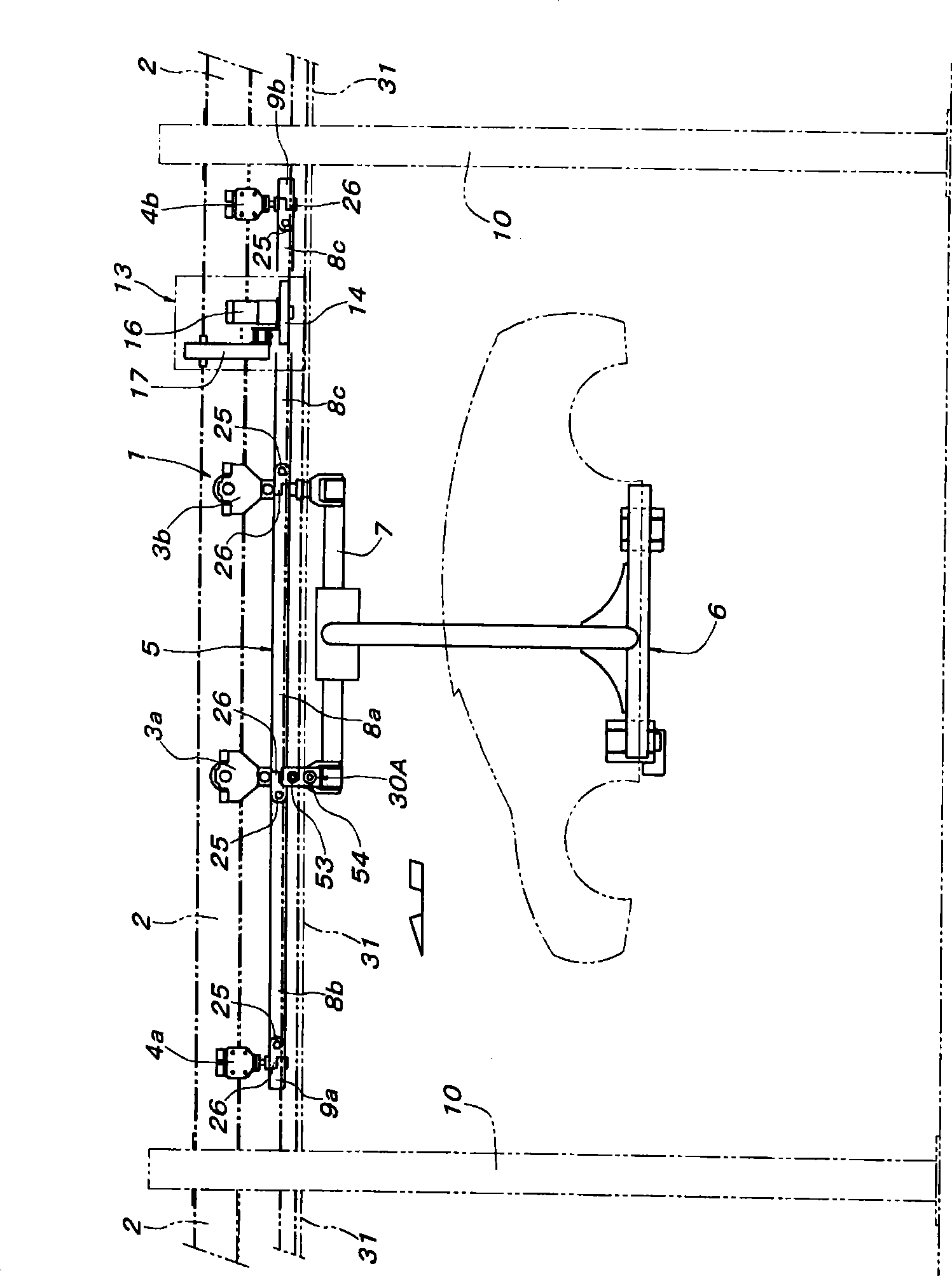
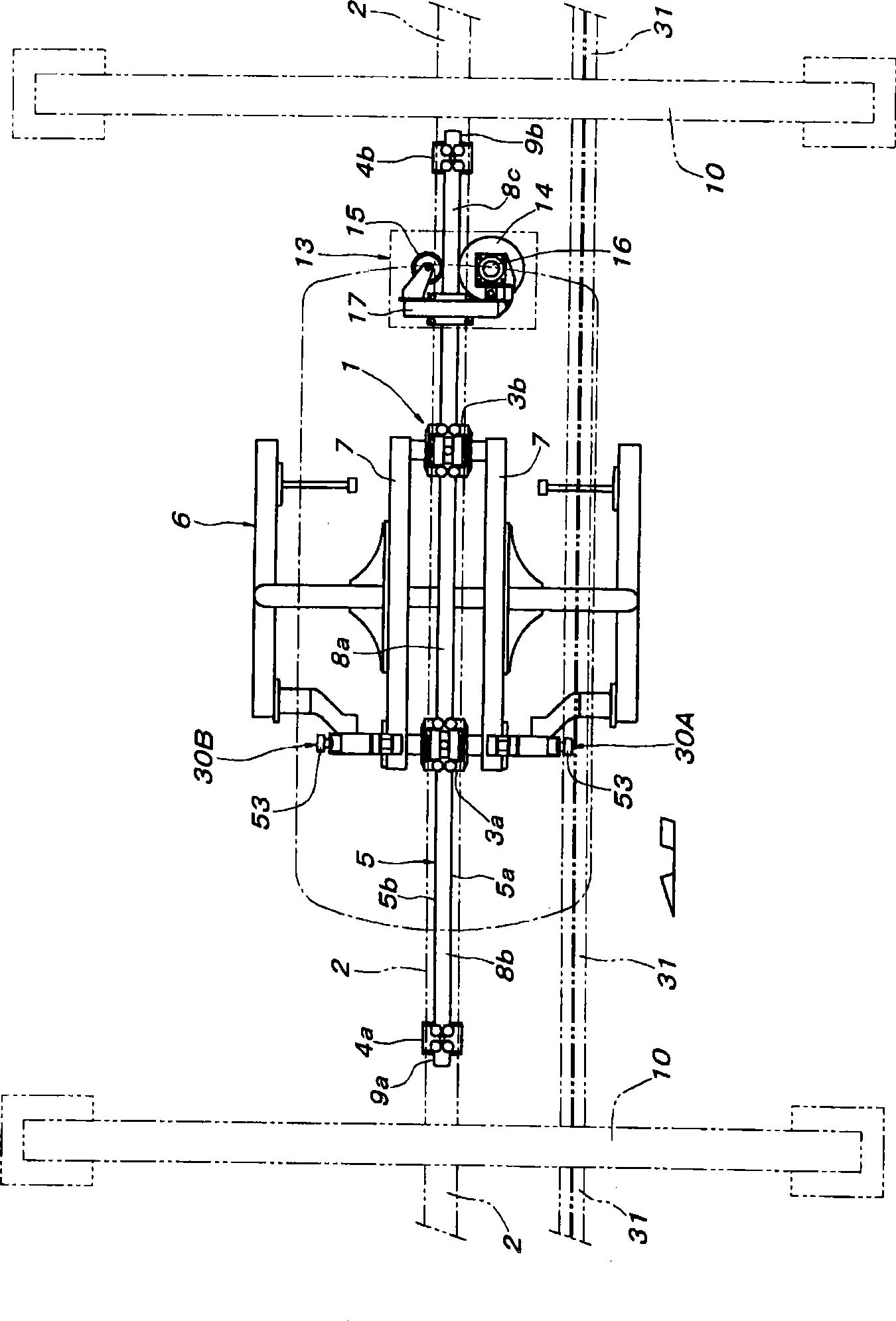
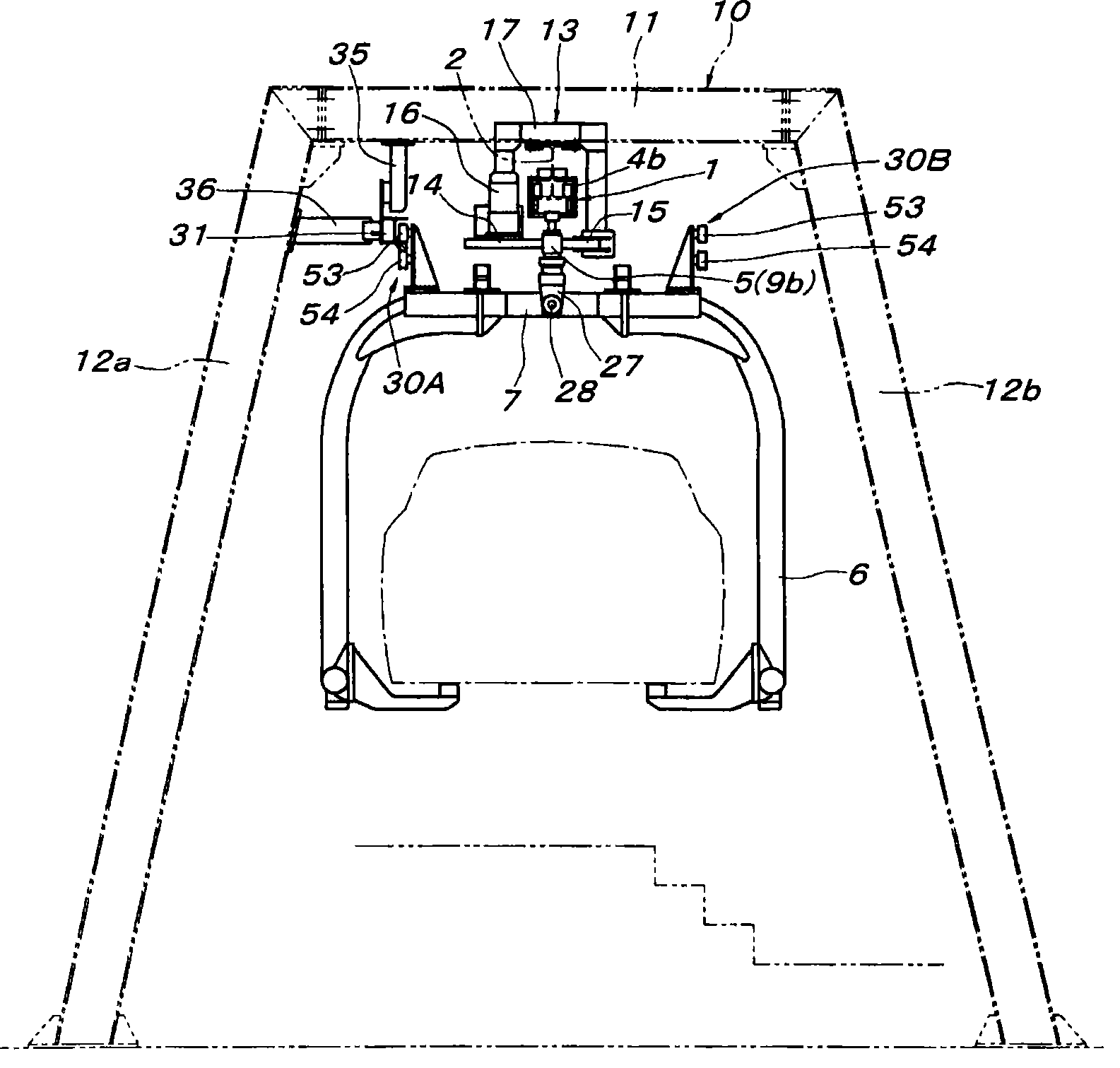
[0038] see Figure 1 to Figure 3 Shown are side schematic diagrams, top schematic diagrams, and rear schematic diagrams of the moving body for conveyance and the friction drive mechanism in the moving path, respectively.

[0039] exist Figure 1 ~ Figure 3 Among them, the mobile body 1 for conveying includes four trolleys (ie, a pair of front and rear load trolleys 3a, 3b in the middle, and a pair of front and rear trolleys 3a, 3b) that can be moved by fastening on the mobile guide rail 2 erected at a predetermined height on the ground. The unloaded trolleys 4a and 4b at the en...


PUM


Abstract

A suspension conveyance apparatus has a conveying traveling body movably supported on a traveling guide rail and a hanger suspended from the conveying traveling body, and an anti-swaying guide rail in parallel with the traveling guide rail, the anti-swaying guide rail is engaged with a roller and prevents lateral swaying of the hanger. The anti-swaying guide rail is installed on only one of the right and left sides of the traveling guide rail and includes a horizontal flat rail surface and a circular rail surface curvedly protruding in the vertically opposite direction of the horizontal flat rail surface, and a flat peripheral surface roller adjoining to the horizontal flat rail surface and rolling and an hourglass-shaped peripheral surface roller fitted to the circular rail surface are provided as the roller.

Description

technical field [0001] The present invention relates to a suspended conveying device, in particular to a suspended conveying device comprising a conveying moving body movably supported by a moving guide rail and a conveyed object support tool suspended from the conveying moving body . Background technique [0002] As described in Japanese Patent Application Laid-Open No. 2003-267208 as the Japanese Patent Laid-Open Gazette, this type of suspended conveyance device includes a conveyance mobile body and a conveyed object supporting tool (hanger) suspended thereon. In the conveying path using such a moving body for conveying, for example, in a production line for component mounting of a conveyed object supported by a conveyed object support tool, there is a device for preventing the conveyed object support tool from swinging in the left and right directions. anti-swing mechanism. In addition, in the above-mentioned hang-type conveying device described in the above publication...

Claims


Application Information

Patent Timeline
Patent Type & Authority Applications(China)
IPC IPC(8): B61B10/02B65G35/06
CPCB62D65/18B61B13/127
Inventor 西原重善须乡智广
Owner DAIFUKU CO LTD
Why Eureka
Try Eureka