Lockset

A technology of locks and lock cylinders, applied in the field of locks, which can solve the problems of large length, complex structure, and large volume of the lock sleeve, and achieve the effect of simplifying the structure and saving materials

Active Publication Date: 2009-08-19
佛山市顺德区皇力五金电器有限公司
View PDF1 Cites 3 Cited by
  • Summary
  • Abstract
  • Description
  • Claims
  • Application Information

AI Technical Summary

Problems solved by technology

Existing problems: complex structure and large volume, that is, the length of the lock sleeve is large

Method used


Image

  • Lockset
  • Lockset
  • Lockset

Examples


Embodiment 1

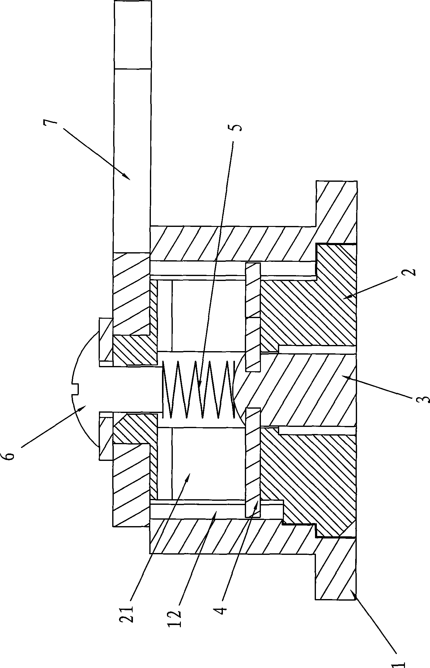
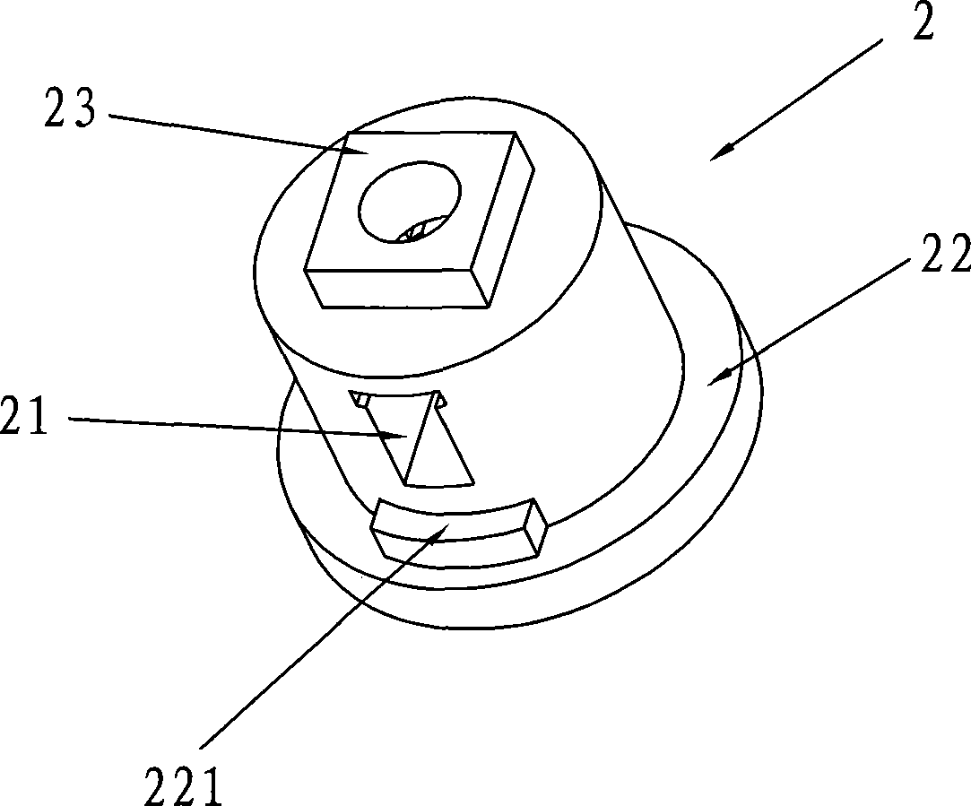
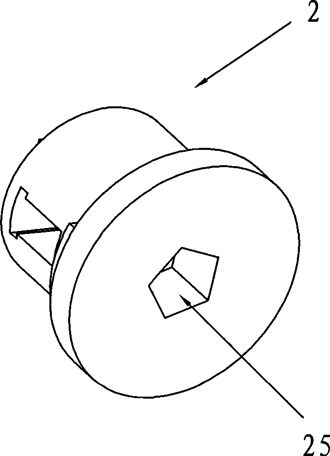
[0021] Such as figure 1 Shown, a kind of lockset comprises lock casing 1, lock core 2, jacking shaft 3, spring 5 and dead bolt 7, and lock core 2 is installed in the lock sleeve 1, and jacking shaft 3 is installed in the lock core 2; figure 2 , image 3 , Figure 4 As shown, there is a top shaft hole 24 on the lock core 2, a key hole 25 connected with the top shaft hole, an axial guide hole 21 penetrating in the radial direction is arranged on the lock core 2, and the key hole end of the lock core 2 has a guide Plate 22, the other end has deadbolt seat 23;

[0022] Such as Figure 5 , Figure 6 As shown, there is a guide platform 11 at the front end of the lock sleeve 1 that cooperates with the keyhole end of the lock cylinder, and a rotating cavity 13 for the sliding piece at the rear end of the lock sleeve. There can be two or four evenly distributed along the circle as required.

[0023] Also includes a sliding piece 4, one end of the top shaft 3 is fixedly connected...

Embodiment 2

[0026] As a further improvement, such as figure 2 , image 3 , Figure 4 As shown, there is a guide stop block 221 on the guide plate 22 of the lock cylinder 2; Figure 7 As shown, the guide platform 11 has a guide limit groove 111 , and the guide stop block 221 cooperates with the guide limit groove 111 . The guide limit groove 11 is a 90-degree arc. Top shaft can rotate 90 degree angles with lock core 2 like this. The guide limit groove can also be a 180-degree arc.

[0027] When the present embodiment is in use, the lock cylinder 2 rotates 90 degrees. or 180 degrees.

Embodiment 3

[0029] As a further improvement, such as Figure 8 As shown, there are two rotating grooves 14 of the sliding piece 4 on the inner wall of the rotating chamber 13 at the rear end of the lock sleeve 1, and the rotating grooves 14 are arranged symmetrically on a diameter line; The rotating cavity 13 between the 131 constitutes a rotating groove 14; the sliding plate 4 rotates in the rotating groove 14 at an angle of 90 degrees. The rotating groove 14 plays the role of limiting and stopping the sliding plate 4 . The guide limit groove 11 is a 90-degree arc.

[0030] When the present embodiment is in use, the lock core 2 rotates 90 degrees, and the sliding plate 4 rotates 90 degrees in the rotating groove 14 .


PUM


Abstract

A lockset comprises a lock sleeve, a lock core, an apical axis, a spring and a lock tongue. The lock core is provided with an axial guide hole running through along the radial direction; the lock-key hole end of the lock core is provided with a guide disk and the other end of the lock core is provided with a lock tongue base; the front end of the lock sleeve coordinating with the lock-key hole end of the lock core is provided with a guide platform and the rear end thereof is provided with a rotary cavity; a guide slot along the axial direction is arranged on the inner wall of the lock sleeve. The lockset also comprises a slider; the slider is fixedly connected with one end of the apical axis, is positioned in an apical axis hole and stretches out of the guide hole and coordinates with the guide hole in a sliding way; the slider coordinates with the guide slot and the guide disk coordinates with the guide platform. Due to such a structure, the separation of the lock core from the lock sleeve can be realized after the slider moves comparatively short distance in the guide slot of the lock sleeve and the apical axis moves comparatively short distance in the lock core. Compared with that the apical axis has a cone and a middle part in the prior art, the length of the apical axis is shortened, so is the length of the lock sleeve and the lock core, and the materials are saved. Compared with the prior art, pintels and stop pins are saved, the structure is simplified and the lockset can adapt to thinner door bodies.

Description

technical field [0001] The invention relates to a lock, in particular to a lock used on the doors of refrigerators, electric cabinets and toolboxes. Background technique [0002] Existing technology at present, Chinese patent ZL02249944.X, invention name: lockset, it is made up of lock sleeve, lock cylinder, jacking shaft, spring, lock bead, limit nail, buckle nail, dead bolt and lock key. Existing problems: complex structure and large volume, that is, the length of the lock sleeve is large. Contents of the invention [0003] The purpose of the present invention is to provide a lock, which not only has a simple structure, is small in volume, saves materials, but also has a small moving distance of the jacking shaft. [0004] The present invention is achieved in the following way: a lockset includes a lock sleeve, a lock core, a jack shaft, a spring and a dead bolt, the lock core is installed in the lock sleeve, the jack shaft is installed in the lock core, and the lock co...

Claims


Application Information

Patent Timeline
Patent Type & Authority Applications(China)
IPC IPC(8): E05B65/44
Inventor 何厚荣
Owner 佛山市顺德区皇力五金电器有限公司
Why Eureka
Try Eureka