Gear change control system of automatic transmission

A technology for automatic transmissions and control systems, applied in the direction of transmission control, elements with teeth, belts/chains/gears, etc., which can solve problems such as difficult to move shift protrusions

Inactive Publication Date: 2009-08-19
MITSUBISHI MOTORS CORP
View PDF1 Cites 1 Cited by
  • Summary
  • Abstract
  • Description
  • Claims
  • Application Information

AI Technical Summary

Problems solved by technology

Next, in the case where the interval L1 between the pair of claws 121 of JP-A-2001-304411 increases, the force P1 acting on the claws 121 in the shifting direction The shift direction moves the shift protrusion connected to the claw portion 121

Method used


Image

  • Gear change control system of automatic transmission
  • Gear change control system of automatic transmission
  • Gear change control system of automatic transmission

Examples


Embodiment Construction

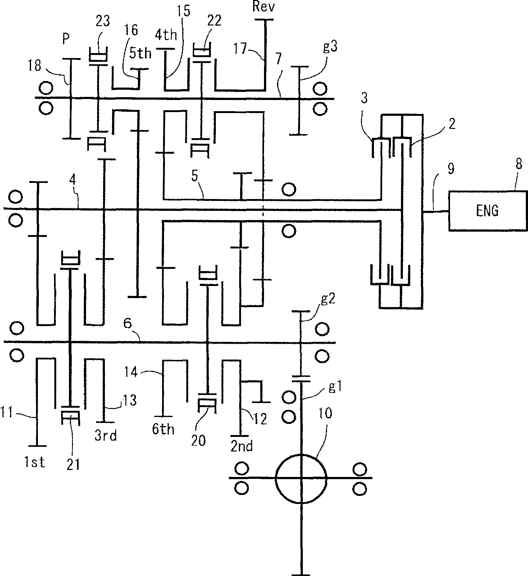
[0042] Subsequently, the shift control system of an automatic transmission as an embodiment of the present invention will refer to figure 1 and 2 to describe.

[0043] like figure 1 The automatic transmission 1 shown is a double clutch transmission and comprises two clutches 2, 3, two main shafts 4, 5 and two layshafts 6, 7 arranged concentrically with each other. Power is transmitted from a driving force transmission shaft 9 that transmits driving force from an engine 8 to the first main shaft 4 through a first clutch 2 , and power is transmitted from the driving force transmission shaft 9 to the second main shaft 5 through a second clutch 3 . Note that the two clutches are controlled to be engaged or disengaged by control circuits not shown (eg, hydraulic, electrical, or mechanical control circuits).

[0044] The first layshaft 6 and the second layshaft 7 are arranged spaced apart from each other such that their axes are parallel to the first main shaft 4 and the second...


PUM


Abstract

A gear change control system of an automatic transmission, include: a shift member, including a shaft portion which is s disposed in such a manner that a selection axis thereof is oriented in a selecting direction and including an arm portion; shift fork portions, operable to make gear shifts of gears; shift rail members, connected to the sift fork portions and arranged in such a manner that shift axes thereof are oriented in a shifting direction; and shift lug members, projecting from the shift rail members and including pillar-shaped portions. The arm portion swings about the selection axisto apply a pressure in the shifting direction from one side of the pillar-shaped portion so as to cause the shift fork portion to perform a shift making operation, and to apply a pressure in the shifting direction from the other side of the pillar-shaped portion so as to cause the shift fork portion to perform a shift withdrawing operation.

Description

technical field [0001] The invention relates to a shift control system of an automatic transmission arranged on a vehicle transmission system (drive train). Background technique [0002] Existing mechanical automatic transmissions do not use a torque converter as a transmission provided in a vehicle transmission system. [0003] This mechanical automatic transmission performs the actuation of shift control (selection and execution of gear shift) and the engagement and disengagement of the clutches performed in the manual transmission by an actuator, thereby eliminating the need for torque mutator needs. For example, if Figure 8A and 8B As shown, the shift control system of the automatic transmission includes a shift lever (shift shaft) 100 movable in the shift direction sf and the selection direction se, shift protrusions (shift lugs) 120 and shift forks 131, 132, 133, Shift lugs 120 are respectively formed on and protrude radially outward from a part of a plurality of s...

Claims


Application Information

Patent Timeline
Patent Type & Authority Applications(China)
IPC IPC(8): F16H63/20
CPCF16H61/32F16H61/688F16H2063/025F16H2061/2892F16H2063/208F16H63/20Y10T74/20104Y10T74/20183Y10T74/19251Y10T74/20177F16H63/30F16H63/02
Inventor 藤本将司新谷昌则
Owner MITSUBISHI MOTORS CORP
Why Eureka
Try Eureka