Apparatus for detecting engine speed by exhaust pressure

A technology of engine speed and exhaust pressure, which is applied in the direction of engine testing, measuring devices, and devices using fluids, etc. It can solve problems such as complex use process, deviation of test results, interference, etc., and achieve simple and convenient use and ensure accuracy , easy to carry effect

Inactive Publication Date: 2009-08-19
北京品今资本管理股份有限公司
View PDF0 Cites 3 Cited by
  • Summary
  • Abstract
  • Description
  • Claims
  • Application Information

AI Technical Summary

Problems solved by technology

[0004] However, the existing measuring instruments must contact or sense the moving parts of the engine, all of which are based on mechanical principles, the use process is relatively complicated, and it is difficult to carry and install the instrument
Moreover, the existing measuring instruments must contact or sense the rotating parts of the engine, and are installed and fixed in the car body near the engine, especially in the car body after assembly, it is extremely inconvenient to disassemble, maintain and install
In order to solve the above problems, a method and device for detecting the speed of the engine through the noise of the engine have appeared. Although the use of this device is relatively simple, the engine speed can also be measured according to the noise in theory, but it is easy to be interfered by external factors, such as , other sound signals are more likely to affect the detection results, causing large deviations in the detection results

Method used


Image

  • Apparatus for detecting engine speed by exhaust pressure
  • Apparatus for detecting engine speed by exhaust pressure
  • Apparatus for detecting engine speed by exhaust pressure

Examples


Embodiment Construction

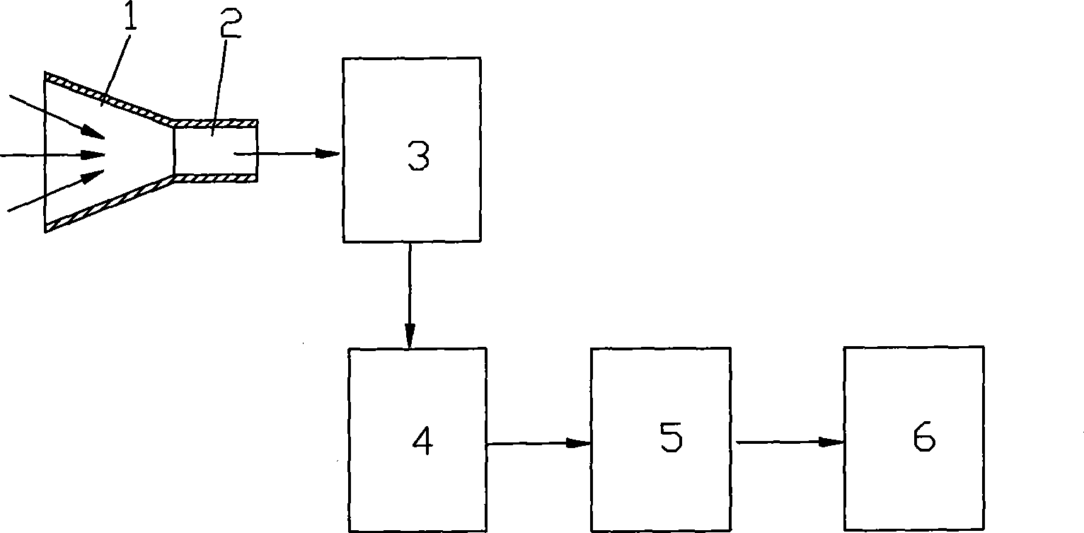
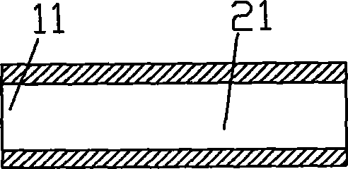
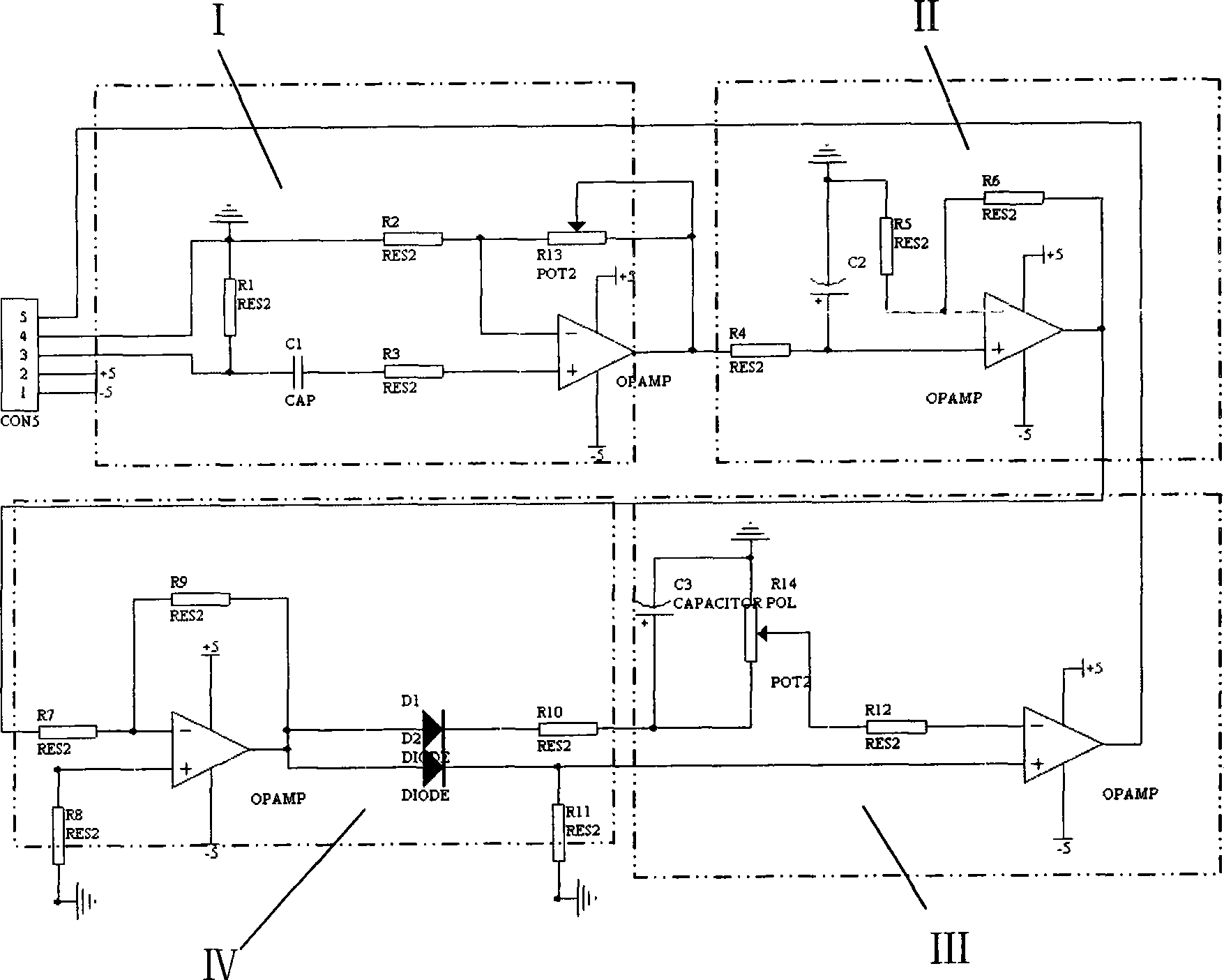
[0017] figure 1 It is a schematic block diagram of the present invention, image 3 It is a schematic diagram of the signal processor circuit of the present invention, as shown in the figure: the device for detecting the engine speed through the exhaust pressure of the present embodiment includes an engine exhaust pressure acquisition device, a pressure sensor 3, a signal processor 4, a central processing unit 5 and Display 6, pressure sensor 3 collects the pressure signal of the exhaust gas in the engine exhaust pressure acquisition device and converts the pressure signal into an electrical signal. Value characteristics, by connecting to the bridge circuit to change the change of its resistance value to the change of the current signal (the range of the current signal is 0~20mA), the electrical signal is transmitted to the signal processor 4 and converted into a digital pulse signal, the digital pulse signal It is transmitted to the central processor 5 to calculate according ...


PUM


Abstract

The invention discloses a device which detects the rotating speed of an engine by exhaust pressure, comprising an engine tail gas pressure collecting device, a pressure sensor, a signal processor, a central processor and a displayer; wherein, the pressure sensor collects the pressure signal of the tail gas in the engine tail gas pressure collecting device and converts the pressure signal into an electric signal which is transmitted to the signal processor so as to be converted into a digital pulse signal which is transmitted to the central processor, and the central processor calculates and displays the rotating speed value by the displayer according to the pulse signal; the device collects the frequency signal of engine exhaust pressure by utilizing the proportion relationship of engine exhaust frequency and rotating speed and the correspondence relationship of transient increasing and reducing of exhaust pressure and the frequency, thus obtaining a rotating speed signal, avoiding influence of external factor on the detection result, guaranteeing the accuracy of the detection result, being simple and convenient for use during detection, and being capable of directly testing the rotating speed of the vehicle engine on any random occasion; and the device has small volume and convenient carrying.

Description

technical field [0001] The invention relates to a device for detecting engine performance, in particular to a device for detecting engine speed through exhaust pressure. Background technique [0002] The engine speed is an important performance index of the engine. During the production and maintenance process, the engine speed needs to be tested. [0003] In the prior art, the engine speed test instrument is mainly composed of a sensor and a corresponding circuit. The sensor directly senses the movement of the moving parts of the engine, and the speed signal is output after being processed by the processing circuit. The existing engine speed measuring instruments can basically achieve accurate measurement. [0004] However, the existing measuring instruments must contact or sense the moving parts of the engine, all of which are based on mechanical principles, the use process is relatively complicated, and it is difficult to carry and install the instrument. Moreover, the ...

Claims


Application Information

Patent Timeline
Patent Type & Authority Applications(China)
IPC IPC(8): G01P3/26G01M15/00
Inventor 何平
Owner 北京品今资本管理股份有限公司
Why Eureka
Try Eureka