Elevator apparatus
A technology for elevators and installation parts, which is applied to elevators, transportation and packaging, elevators, etc. in buildings. It can solve the problems of increasing the size of guide rails, increasing manufacturing costs and installation costs, and achieve the effect of reducing bending moments.
- Summary
- Abstract
- Description
- Claims
- Application Information
AI Technical Summary
Problems solved by technology
Method used
Image

Examples
Embodiment approach 1
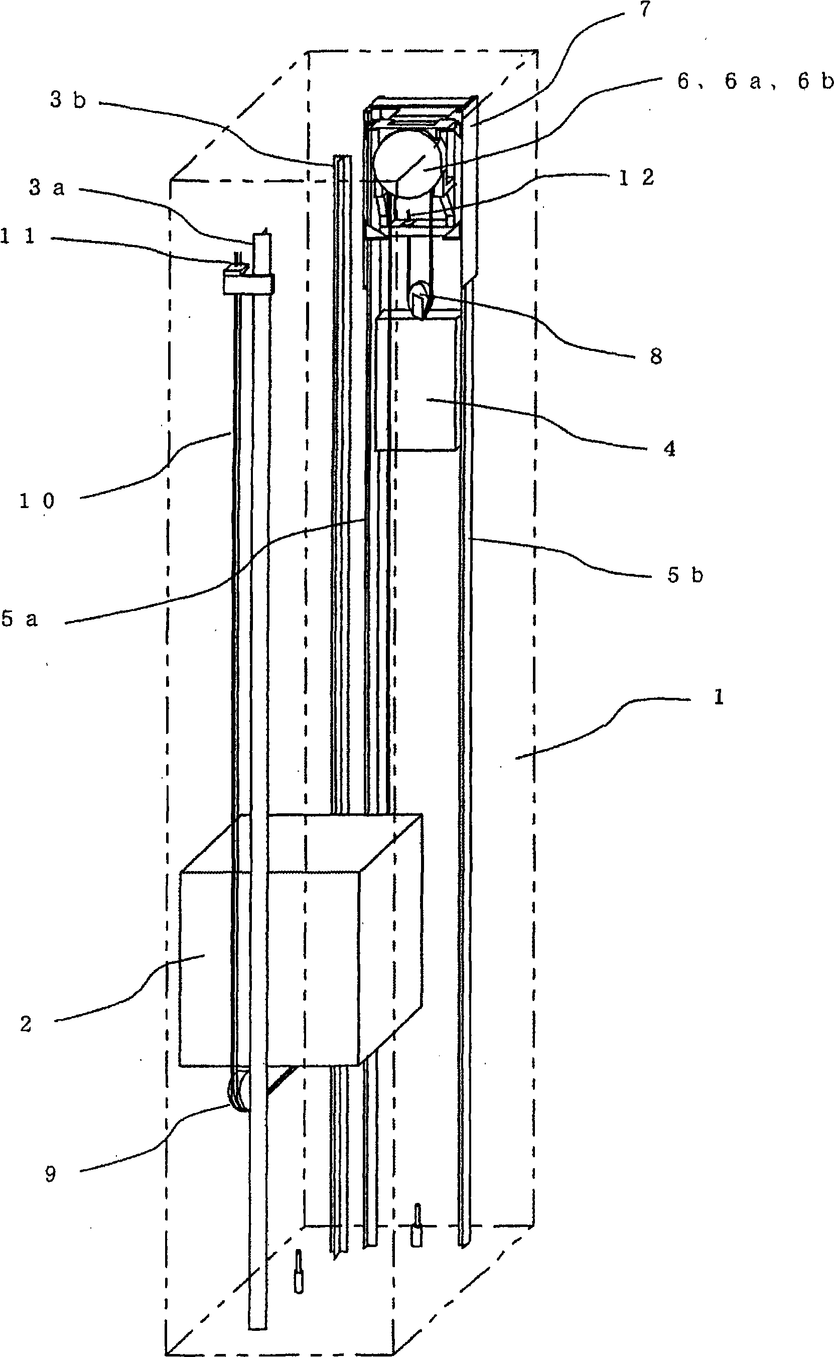
[0031] figure 1 It is a general configuration diagram showing an elevator apparatus according to Embodiment 1 for carrying out the present invention.
[0032] exist figure 1 Among them, the hoistway 1 has: the car 2, which is used to carry passengers and lift; the guide rails 3a and 3b of the car 2, which are respectively arranged on both sides of the car 2, are used to guide the lifting of the car 2; the counterweight 4, which lifts in the direction opposite to the lifting direction of the car 2; and the guide rails 5a, 5b of the counterweight 4, which are respectively arranged on both sides of the counterweight 4, for guiding the lifting of the counterweight 4. On the upper side of the counterweight 4 and in the upper part of the hoistway 1, a traction machine 6 serving as a power source for raising and lowering the car 2 and the counterweight 4 is provided. The hoisting machine 6 has a driving sheave 6a around which the suspension unit 10 suspending the car 2 and the co...
Embodiment approach 2
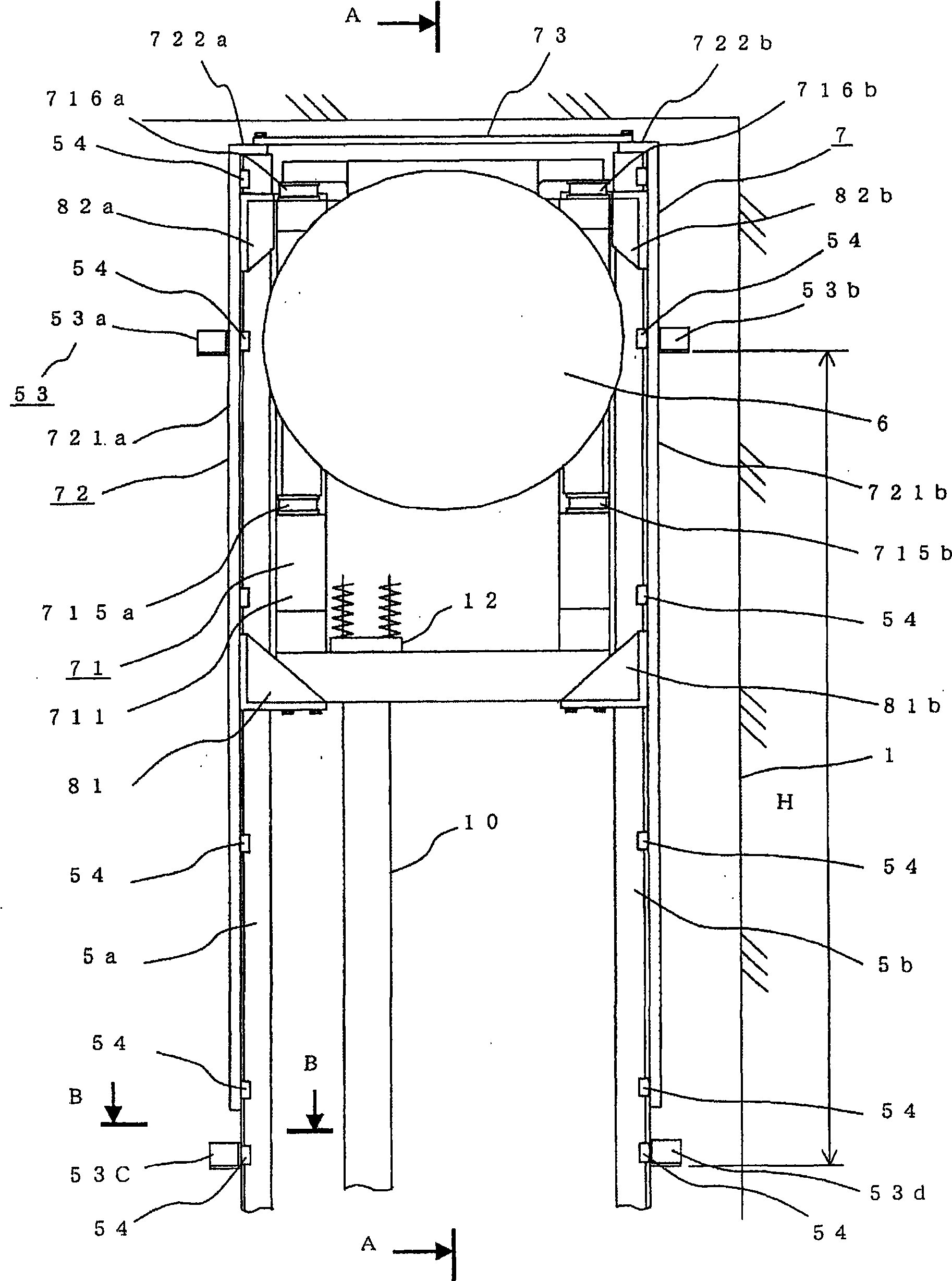
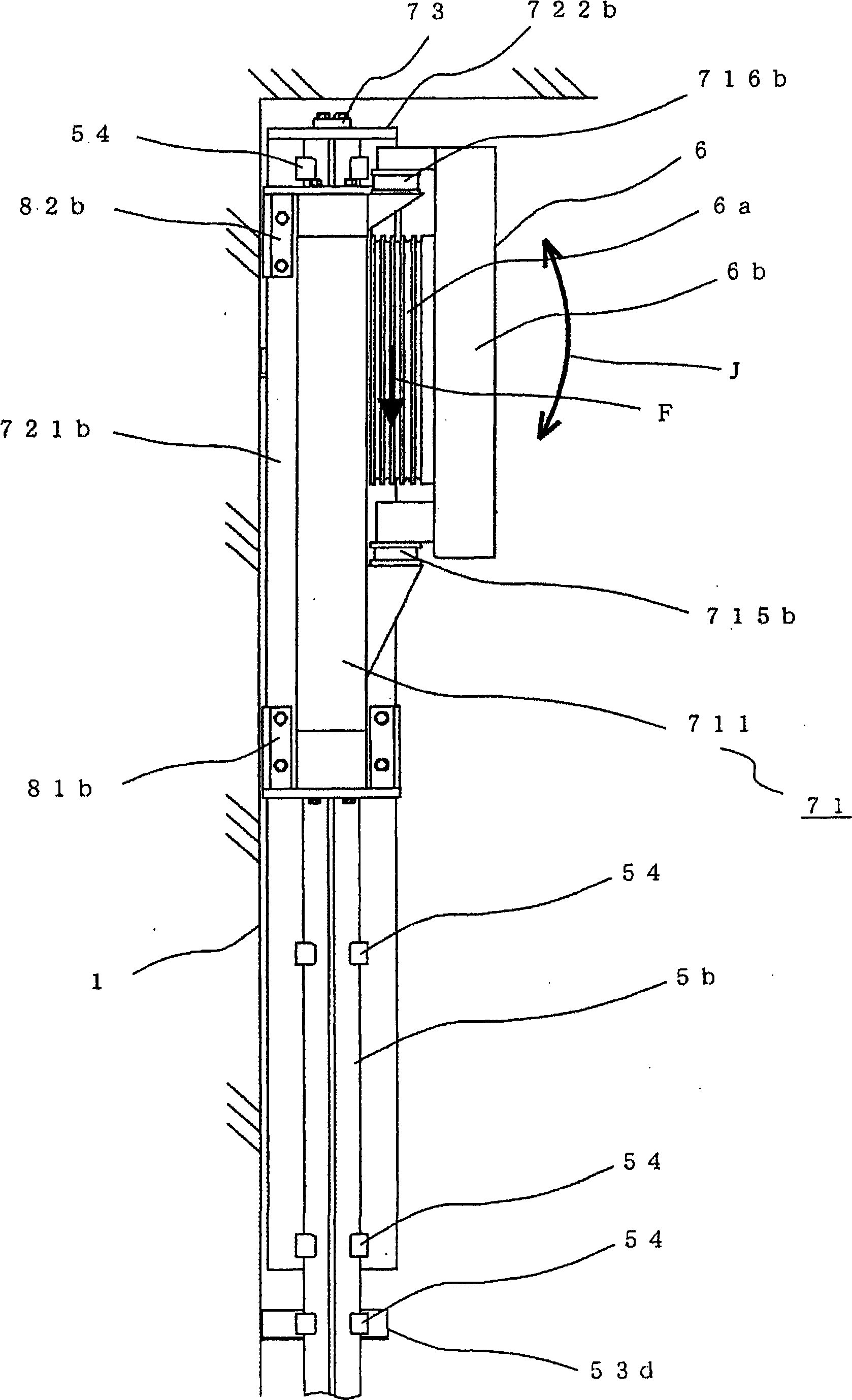
[0073] Figure 12 , Figure 13 , Figure 14 , Figure 15 with Figure 16 It is a figure which shows the hoisting machine installation mechanism of the elevator apparatus concerning Embodiment 2 of this invention, Figure 12 is the main view, Figure 13 yes Figure 12 Section E—E in. Figure 14 It is a front view of an enlarged main part of the upper part of the traction machine installation mechanism, Figure 15 is the side view, Figure 16 yes means Figure 14 The diagram of section G—G in . Regarding Embodiment 2, compared to Embodiment 1, a partial contact portion 74 , a restricting body 75 , and an adjustment member 76 are provided on the upper portion of a rail mounting portion 72 . Other points are the same as those in Embodiment 1, and description thereof will be omitted. In addition, the same code|symbol as Embodiment 1 shows the corresponding part.
[0074] use Figure 14 , Figure 15 with Figure 16 The partial contact portion 74 on the side of the gui...
Embodiment approach 3
[0084] Figure 17 , Figure 18 is a diagram showing an elevator apparatus according to Embodiment 3 of the present invention, Figure 15 is the overall structure diagram of the elevator device, Figure 16 It is an enlarged view of the installation mechanism of the traction machine.
[0085] In Embodiments 1 and 2, the hoisting machine mounting mechanisms 7 and 13 are installed on the guide rails 5a and 5b of the counterweight, but the present invention is not limited thereto and may be installed on the guide rails 3a and 3b of the car 2 . Embodiment 3 shows an example of this case. Other points are the same as Embodiments 1 and 2, and detailed descriptions are omitted. In addition, the same reference numerals as in Embodiments 1 and 2 denote corresponding parts.
[0086] In the figure, the upper part of the car 2 is provided with a car suspension wheel 14, and one end of the suspension unit 10 is fixed on the suspension unit installation part 11 arranged on the upper part...
PUM
 Abstract
Description
Claims
Application Information
 - R&D
- Intellectual Property
- Life Sciences
- Materials
- Tech Scout
- Unparalleled Data Quality
- Higher Quality Content
- 60% Fewer Hallucinations
Browse by: Latest US Patents, China's latest patents, Technical Efficacy Thesaurus, Application Domain, Technology Topic, Popular Technical Reports.
© 2025 PatSnap. All rights reserved.Legal|Privacy policy|Modern Slavery Act Transparency Statement|Sitemap|About US| Contact US: help@patsnap.com