
Double steering rigid suspended car axle assembly
A double-steering and assembly technology, applied in axles, elastic suspensions, suspensions, etc., can solve the problems of easy lifting of tires and large turning radius, and achieve the effect of small turning radius, uniform force, and optimized design structure
- Summary
- Abstract
- Description
- Claims
- Application Information
AI Technical Summary
Problems solved by technology
Method used
Image

Examples
Embodiment Construction
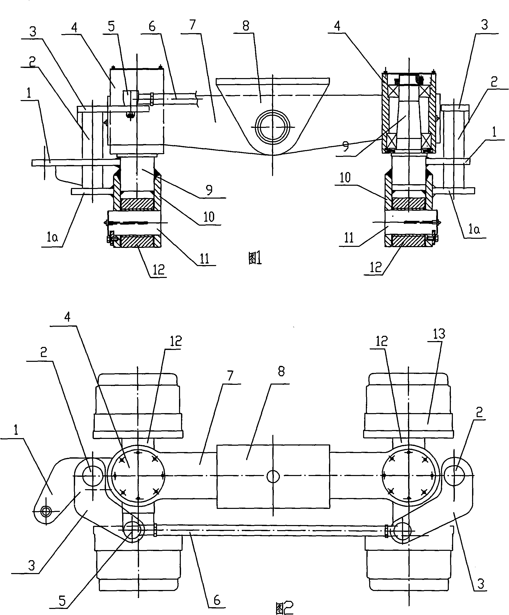
[0012] Such as figure 1 , figure 2 As shown, the double steering rigid suspension axle assembly provided by the present invention includes the original balance beam 7 and the connected tripod 8, and the two ends of the balance beam are connected with the vertical shaft assembly 4 respectively, so that the balance beam can swing up and down around the center of the tripod .
[0013] The present invention is characterized in that: each vertical shaft assembly 4 adopts a bearing to movably connect the vertical shaft 9, and each vertical shaft 9 is fixedly connected with a steering arm 1 and a reinforcing arm 1a, and each steering arm 1 and the reinforcing arm 1a are jointly connected with a rotating shaft 2. The upper end of each rotating shaft 2 is hinged to a crank arm 3, and the left and right crank arms 3 are respectively hinged to a pull rod 6 with a pin shaft 5. When the steering arm 1 on one side is powered, the vertical shaft 9 on both sides is driven to rotate synchro...
PUM
 Abstract
Description
Claims
Application Information