
Rotary sprayer

A sprayer and liquid technology, applied in the field of centrifugal sprayers, can solve the problems of easy blockage of pipes and uneven wetting of workpieces, and achieve the effect of preventing the formation of droplets

Active Publication Date: 2009-09-02
WEITMANN & KONRAD
View PDF2 Cites 6 Cited by
  • Summary
  • Abstract
  • Description
  • Claims
  • Application Information

AI Technical Summary

Problems solved by technology

However, it has proven to have the disadvantage that, in the case of determining the amount of liquid per unit of time, the liquid is no longer released from the pipe continuously but in the form of drops
The addition in the form of drops results in a very intermittent spraying of the liquid, which results in a very uneven wetting of the workpiece, e.g. a paper or textile web, by the spraying liquid
[0004] Another problem is that pipes with very small internal diameters tend to clog due to deposits of impurities or liquid additives transported with the liquid, so that the liquid is no longer transported

Method used


Image

  • Rotary sprayer
  • Rotary sprayer
  • Rotary sprayer

Examples


Embodiment Construction

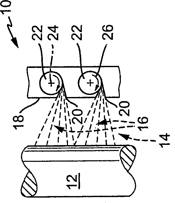
[0022] figure 1 A centrifugal sprayer, generally designated 10 , is shown, with which a workpiece 12 is sprayed with a liquid 14 . exist figure 1 A portion of the liquid shown in , forms an effective working flow 16 with which the workpiece 12 , for example a roll, paper web or fabric web, is wetted. The working flow 16 leaves the housing 18 , not shown in detail, through the perforated plate 20 , wherein a plurality of rotary disks 22 are arranged in the housing 18 , which rotate about an axis of rotation 24 , for example in the direction of the arrow 26 .

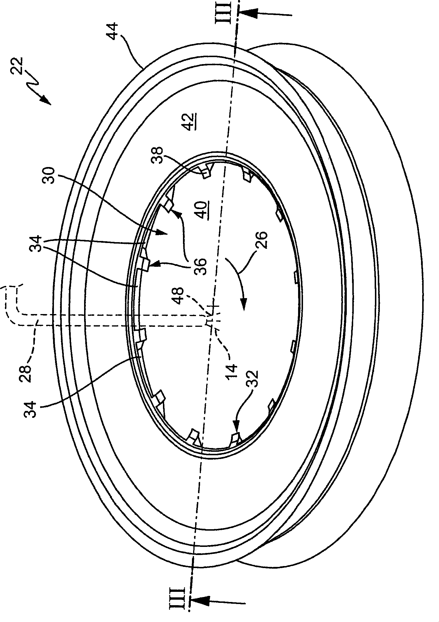
[0023] figure 2 A perspective view of a first embodiment of a carousel 22 is shown, on which the liquid 14 is sent by means of a pipe 28 shown only in a schematic manner. The liquid 14 flows onto a distribution surface designated as a whole by 30 , on which it flows radially outwards and reaches a region 32 in which a plurality of perforations 34 are arranged. Between the perforations 34 is a web 36 which has a web s...


PUM


Abstract

The invention relates to a rotary sprayer, especially a rotary sprayer (10) for fluids (14). The rotary sprayer has a rotating disc (22), a drive (58) for the disc (22), and a supply device (28) for the application of fluid (14) onto the disc (22). The disc (22) has a distribution plane (30) for the fluid (14), and at least one opening (34) is provided in the distribution plane (30), via which a secondary flow (50) of the fluid (14) is separated from the main flow (48) to another plane (46). The disc (22) has a first spray edge (44) for spraying the working flow (52) of the fluid (14) and a second spray edge (54) for spraying the secondary flow (50) of the fluid (14).

Description

technical field [0001] The invention relates to a centrifugal sprayer for liquids. Background technique [0002] A large number of embodiments of centrifugal atomizers for liquids are known. For example in the published publication "Spray Technology ( )", ISBN 3-540-41170-4, page 82 discloses a centrifugal sprayer in which the liquid flow is delivered to a ribbed rotating disk with flow channels so that the liquid utilizes radial The component is centrifugally ejected outward. In the open publication "Spray liquid ( von Flüssigkeiten), ISBN 3-8169-2309-7, on page 74, discloses different embodiments for the turntable, for example designed as a flat disc, a cup open downwards, designed as a perforated or Ribbed disc, or designed as a porous hollow cylinder. Adding liquid is always realized by one or more pipelines anyway. In addition, a kind of material web for wetting movement is disclosed in DE 42 27 136 A1 device, wherein liquid discharge is realized by means of a sp...

Claims


Application Information

Patent Timeline
Patent Type & Authority Applications(China)
IPC IPC(8): B05B3/02B05B12/00B05C5/00
CPCB41F23/02B05B3/1014
Inventor 迈克尔·布林彼得·埃帕谢赖纳·格茨
Owner WEITMANN & KONRAD
Learn More