Retaining apparatus

A technology for holding appliances and processing tools, which is applied in the direction of manufacturing tools, metal processing equipment, optical surface grinders, etc., and can solve the problems of easy falling off of lenses, difficulty in rotating the lens holding appliance and lens, and wear of the outer cylinder

Active Publication Date: 2009-09-02
OLYMPUS CORP
View PDF1 Cites 14 Cited by
  • Summary
  • Abstract
  • Description
  • Claims
  • Application Information

AI Technical Summary

Problems solved by technology

Therefore, as described above, technical problems such as falling off of the lens or wear of the outer cylinder part arise.
[0020] Also, when a lens with a thin edge portion is kept as described in Patent Document 1, since the wear of the outer cylinder portion occurs more quickly, the difference in size between the lens and the outer cylinder portion tends to become large, further making the lens easy to fall off.
[0021] In addition, as the outer diameter of the lens becomes smaller, since the rotational force generated on the lens becomes smaller, it becomes more difficult to rotate the lens holder integrally with the lens via the rotation mechanism provided in the grinding device.

Method used


Image

  • Retaining apparatus
  • Retaining apparatus
  • Retaining apparatus

Examples


Embodiment approach 1

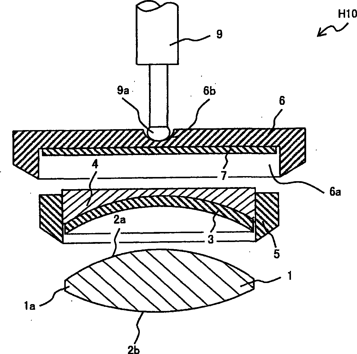
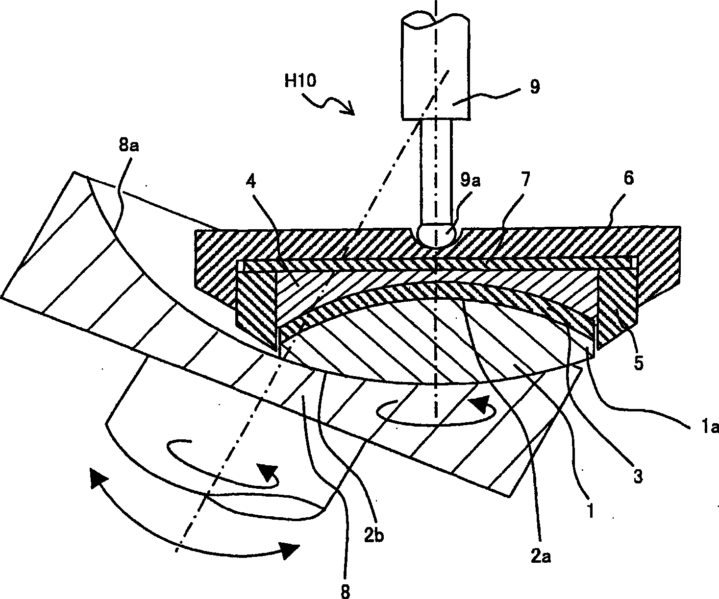
[0101] image 3 It is a cross-sectional view showing an example of the structure and function of the holder as an embodiment of the present invention. The holder H11 disclosed in Embodiment 1 is the above-mentioned Figure 1A and Figure 1B The holder H10 shown in the above example is obtained more concretely, and the same reference numerals are assigned to the common members, and repeated explanations are omitted.

[0102] Should image 3 It shows the situation where lens 1 such as a convex meniscus lens (convex meniscus lenses) is polished by using the holder H11 of this embodiment via the pin 9 used in the conventional grinder.

[0103] (structure)

[0104] A sheet-like member 3 made of superelastic polyurethane having a large coefficient of friction is fastened to the supporting member 4 so as to be in contact with the holding surface 2 a of the lens 1 . In order to make the supporting member 4 support the holding surface 2a of the lens 1, the holding surface 2a has a ...

Embodiment approach 2

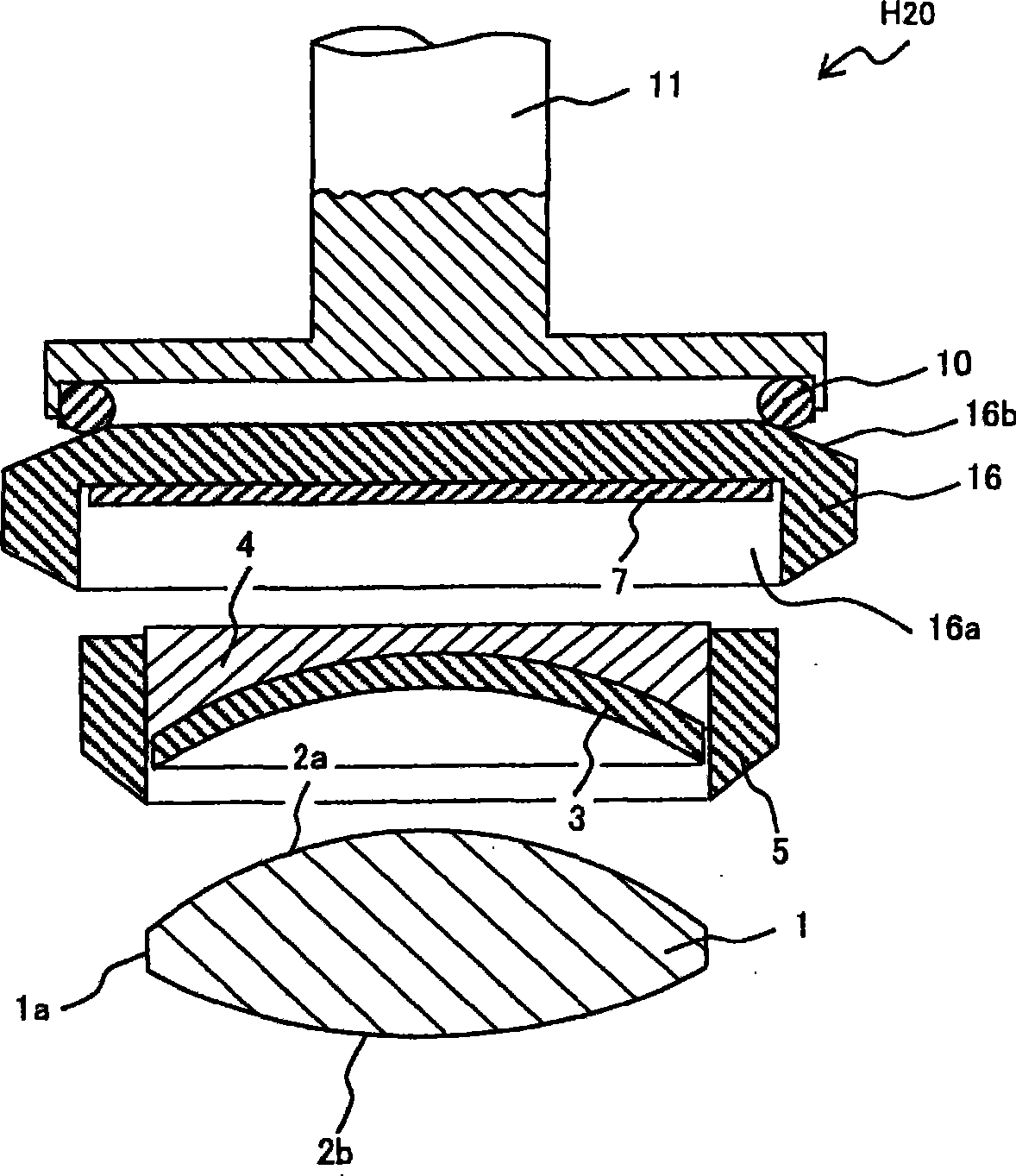
[0133] Figure 4 It is a cross-sectional view showing an example of the structure and function of a holder which is another embodiment of the present invention.

[0134] Should Figure 4 The structure of the holder H21 exemplified in is, for example, corresponding to the lens 1 which is a convex meniscus lens, and the above-mentioned Figure 2A and Figure 2B The structure obtained by making the structure of the holder H20 shown in the example more concrete.

[0135] which is, Figure 4 does not support the lens 1 in a pin structure capable of freely tilting and simultaneously pressing the lens holder, but represents the situation that in the holding unit that presses the lens holder into a freely tilting movement depending on the deformation of the elastic member, The holder H21 of this embodiment is attached, and the convex meniscus lens is ground or lapped.

[0136] about the above Figure 2A and Figure 2B The illustrated holder H20 has components with the same mech...


PUM


Abstract

The invention provides a retaining apparatus for lapping-in between optical elements and process tools. The retaining apparatus comprises: a sheet-shaped component in contact with the retaining surface on the opposite side of the optical element process surface which is in sliding contact with the process tools; a support component for supporting the optical element by said sheet-shaped component; an outer-diameter ring for supporting the outer edge of the optical element supported on said support component; an outer cylinder for supporting the outer-diameter ring in the mode of covering the periphery of the outer-diameter ring, the back of the outer cylinder having a concave spherical surface part cooperated with the outer oscillating axle; and a sliding part located between the outer cylinder and the support component for connecting the two components so that they can rotate.

Description

technical field [0001] The present invention relates to a holder, for example, relates to an effective technology applied to a holder or the like used when grinding or polishing an optical element such as a lens having a curved shape or a planar shape. Background technique [0002] For example, as a lens holder that implements so-called no blocking (no blocking) single-piece lens processing without fastening spherical or planar lenses used in cameras, microscopes, etc. by adhesives, etc., Patent Document 1 discloses a lens holder of a type that is fastened to the tip of a swing shaft (so-called pin) so as to be able to swing, and used. [0003] In addition, Patent Document 2 and Patent Document 3 disclose techniques for forming a support member for supporting a lens in a two-piece structure with respect to the same lens holder. [0004] In the conventional lens holder disclosed in Patent Document 1, the lens is supported by an intermediate piece (Nakama) via a lens support ...

Claims


Application Information

Patent Timeline
Patent Type & Authority Applications(China)
IPC IPC(8): B24B13/005
Inventor 岸田尚之
Owner OLYMPUS CORP
Why Eureka
Try Eureka