LED street lamp

A technology of LED street lamps and lamp bodies, which is applied in the field of lighting, can solve the problems of street lamp installation quantity, height, power average illuminance, and overall uniformity, and achieve the effect of reducing costs and improving economic benefits

Inactive Publication Date: 2009-09-02
NINGBO LIAOYUAN LIGHTING
View PDF2 Cites 25 Cited by
  • Summary
  • Abstract
  • Description
  • Claims
  • Application Information

AI Technical Summary

Problems solved by technology

[0005] The purpose of the present invention is to overcome the defects existing in the existing LED street lamps and provide a LED street lamp with a new structure. The parameters have relatively strict requirements, so that it can give full play to the characteristics of directional light emission and power control

Method used


Image

  • LED street lamp
  • LED street lamp
  • LED street lamp

Examples


no. 1 example

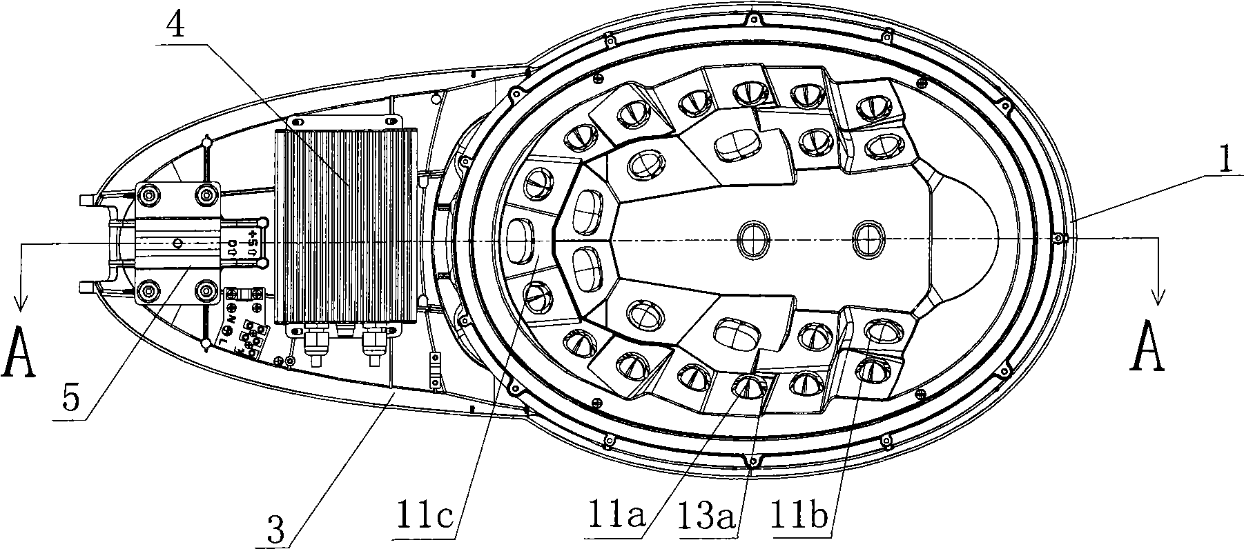
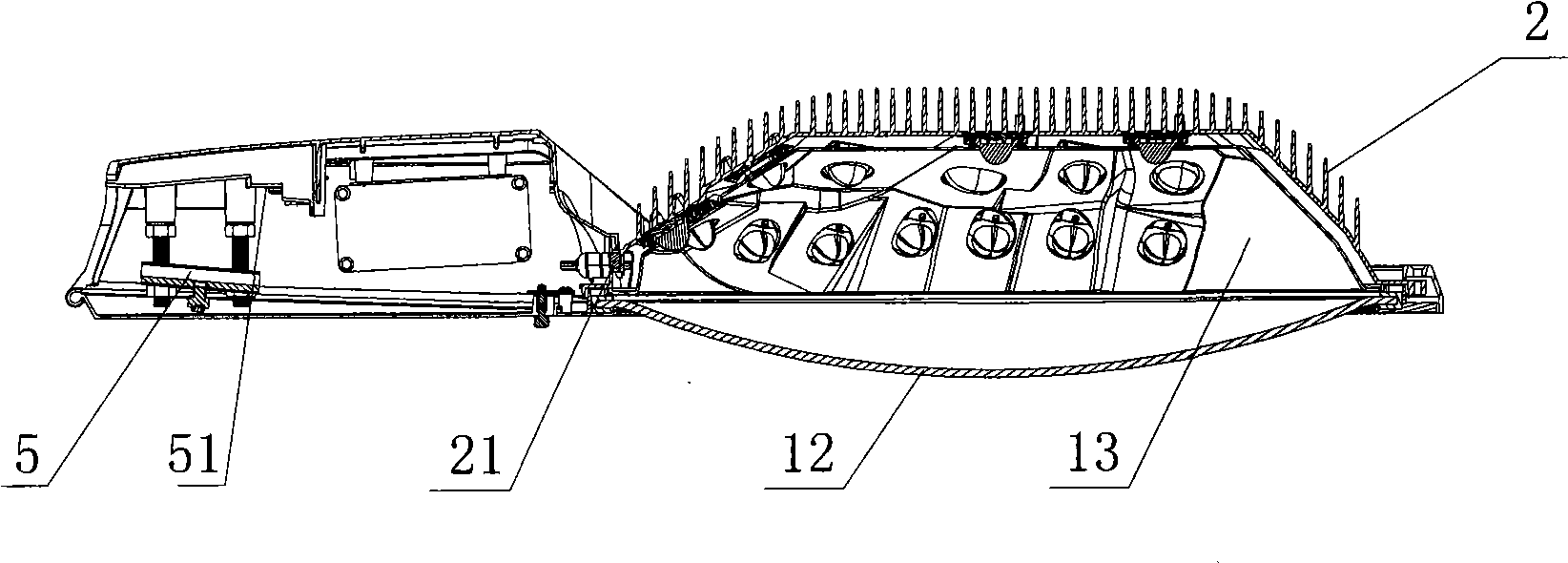
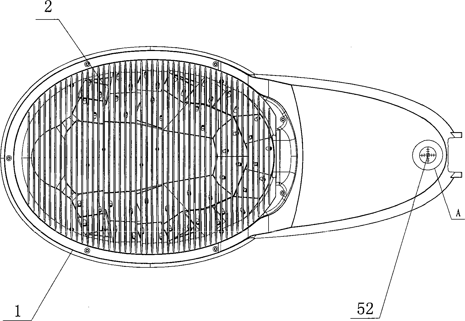
[0084] see figure 1 , figure 2 , image 3 , Figure 4 , Figure 5 As shown, the LED street lamp of the preferred first embodiment of the present invention is mainly composed of a light distribution system 1, a heat dissipation device 2, a lamp body 3, a driving circuit 4, and a lamp installation and adjustment mechanism 5. The external setting of the light distribution system 1 Heat sink 2 (see figure 2 , 3, 4), in order to achieve a better heat dissipation effect, the heat dissipation device 2 and the light distribution system 1 are integrally cast, and the appearance shape can be curved or square. One side of the light distribution system is equipped with LED light-emitting units, and the other side is provided with a cooling device 2 to ensure that each LED light-emitting unit works at a normal temperature. A plurality of light-emitting units are connected in series and parallel and powered by the control of the drive circuit 4 (such as figure 1 , 2 As shown), the...

no. 2 example

[0091] Such as Figures 10a-10b As shown, the LED street lamp of the preferred second embodiment of the present invention is composed of a light distribution system 1, a heat dissipation device 2, a lamp body 3, a drive circuit 4, and a lamp installation and adjustment mechanism 5 (such as Figure 10a shown). The inner surface of the light distribution system 1 is connected by a plurality of block-shaped geometric bodies, and is symmetrically distributed with the center line A-A of the lamp (such as Figure 10a As shown), taking the right half of the center line A-A as an example, the surface normal directions of these block-shaped geometric bodies intersect each other at a certain angle, and several LED light-emitting units 11a, 11b, 11c with different luminous intensities and different beam angles are fixed on the surface , which will make these light emitting units 11a, 11b, 11c all throw light to their respective designated areas (such as Figure 10a shown). The LED lig...

no. 3 example

[0095] Such as Figures 11a-11b As shown, the LED street lamp of the preferred third embodiment of the present invention is composed of a light distribution system 1, a heat dissipation device 2, a lamp body 3, a drive circuit 4, and a lamp installation and adjustment mechanism 5 (such as Figure 11a shown). A cooling device 2 is arranged outside the light distribution system 1. In order to achieve a better heat dissipation effect, the cooling device 2 and the light distribution system 1 are integrally cast, and the appearance is rectangular. One side of the light distribution system is equipped with LED light-emitting units, and the other side is provided with a cooling device 2 to ensure that each LED light-emitting unit works at a normal temperature. Several light-emitting units are connected in series and parallel and powered by the drive circuit 4. The lamp body 3 is provided with an installation adjustment mechanism 5, which can overcome the problem of uneven luminosity...


PUM


Abstract

The invention relates to an LED street lamp applied to roadways, tunnels and other places where the requirement on illumination uniformity is higher. The LED street lamp comprises a light distribution system, a heat sink, a lamp body, a driving circuit and a light fixture installation adjusting mechanism; LED luminescence units are installed on one side of the light distribution system; the axial direction of each LED luminescence unit points at each zone of an object; the LED street lamp is also provided with an optimal optical system required by street illumination light distribution; power supply is controlled by the driving circuit in a shunt control way after the LED luminescence units are connected in series and in parallel; the heat sink is arranged on the other side of the light distribution system, thereby each LED luminescence unit can be ensured to be operated under normal temperature; and by installing the adjusting mechanism and a horizontal alignment device, the problem of ray offset as the position of the light fixture is not in place during the installation of the light fixture can be overcome.

Description

technical field [0001] The invention relates to a street lamp in the field of lighting, in particular to an LED street lamp suitable for main roads, secondary roads and the like that require large areas and require high illuminance and illuminance uniformity. It uses one side of the light distribution system to install LED light-emitting units. The axial direction of each LED light-emitting unit points to each area of ​​the lighting target, and has the best optical system required for road lighting light distribution. Several light-emitting units are connected in series and parallel. The drive circuit splits to control the power supply, and the other side of the light distribution system is equipped with a radiator to ensure that each LED light-emitting unit works at a normal temperature. The uneven luminosity distribution caused by the inaccurate position of the lamp construction and installation can be overcome by installing the adjustment mechanism. However, it has become a...

Claims


Application Information

Patent Timeline
IPC IPC(8): F21S8/00F21V21/00F21V19/00F21V29/00F21W131/103F21Y101/02
CPCF21S8/086F21V19/001F21V29/004F21Y2101/02F21W2131/103Y02B20/72F21V29/75F21Y2115/10
Inventor 朱伯明陈海军孙建江
Owner NINGBO LIAOYUAN LIGHTING
Why Eureka
Try Eureka