System for measuring the output of carbon dioxide

A carbon dioxide and measuring system technology, applied in the direction of measuring device, weighing, registration/indication, etc., can solve the problems of time-consuming and unusable

Inactive Publication Date: 2009-09-02
ORMON CORP
View PDF1 Cites 2 Cited by
  • Summary
  • Abstract
  • Description
  • Claims
  • Application Information

AI Technical Summary

Problems solved by technology

In addition, in order to collect operation data, the carrier needs to manually input, which has the problem of time-consuming
In addition, there are companies that do not acquire operating data, and companies that cannot use the above-mentioned carbon dioxide calculation device

Method used


Image

  • System for measuring the output of carbon dioxide
  • System for measuring the output of carbon dioxide
  • System for measuring the output of carbon dioxide

Examples


Embodiment 1

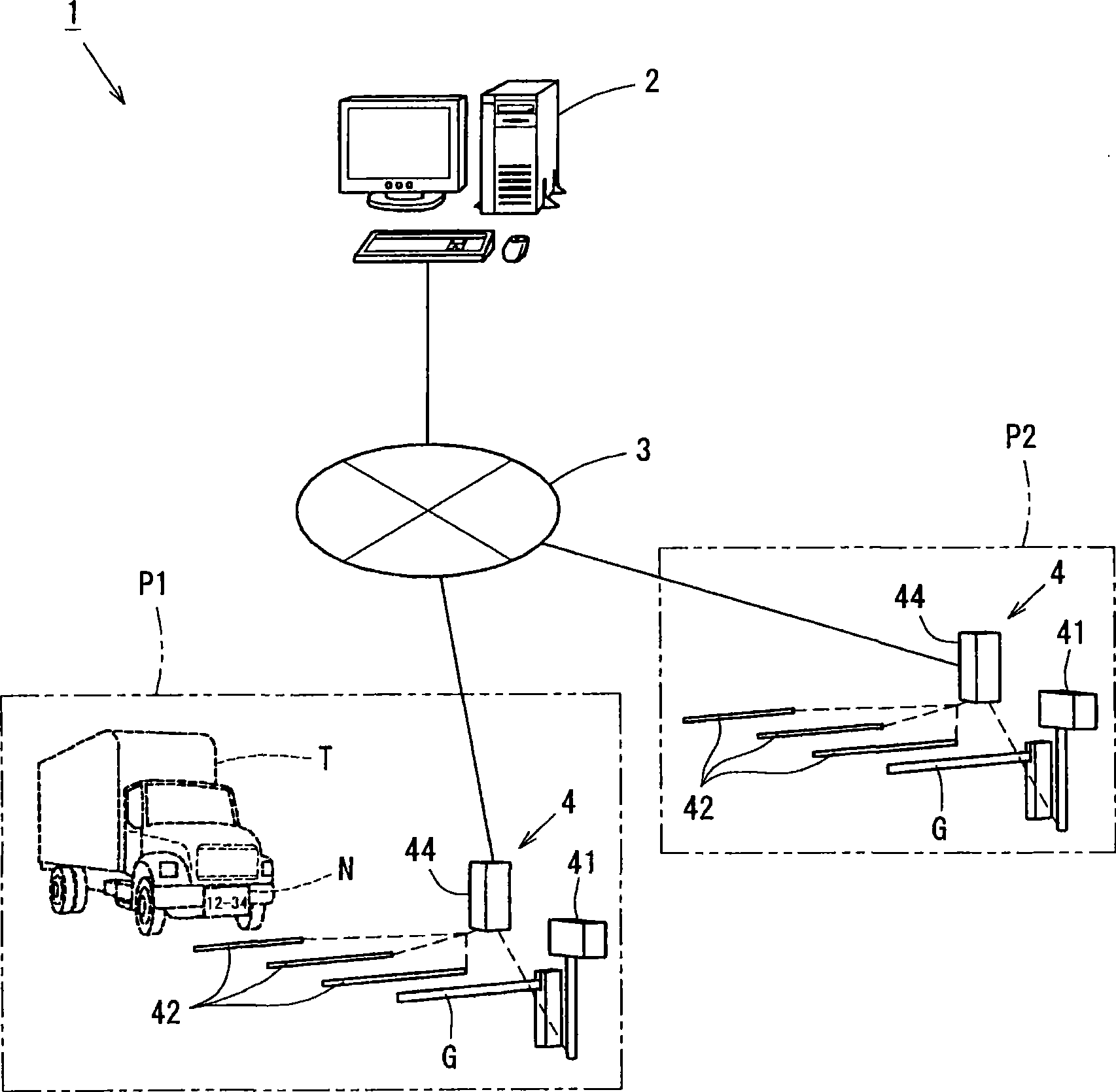
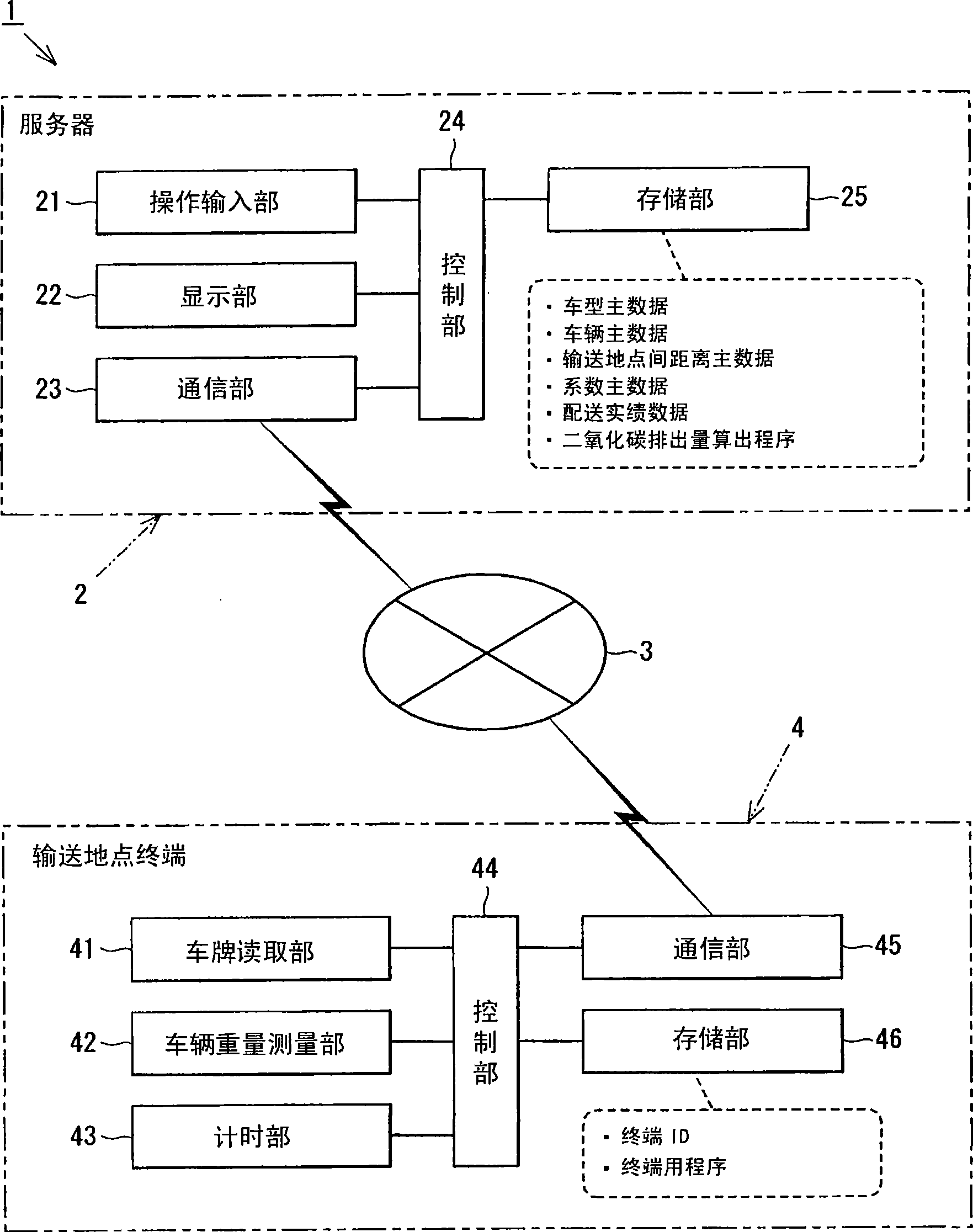
[0047] figure 1 A system configuration diagram showing a carbon dioxide emission measuring system 1, figure 2 A block diagram of the carbon dioxide emission measuring system 1 is shown.

[0048] The carbon dioxide emission measurement system 1 includes a server 2 , delivery point terminals 4 provided at a plurality of delivery points P ( P1 , P2 , . . . ), and the Internet 3 communicably connecting them.

[0049] Such as figure 2 As shown, the server 2 is composed of an operation input unit 21 , a display unit 22 , a communication unit 23 , a control unit 24 and a storage unit 25 .

[0050] The operation input unit 21 is composed of an input device called a keyboard and a mouse, and an input signal is sent to the control unit 24 .

[0051] The display unit 22 is composed of a display device called a CRT display or a liquid crystal display, and displays images (images and characters) based on video signals received from the control unit 24 .

[0052] The communication uni...

Embodiment 2

[0093] Next, combine Figure 6 ~ Figure 12 A carbon dioxide emission measurement system 1 a capable of measuring a highly accurate carbon dioxide emission more conveniently than the carbon dioxide emission measurement system 1 of the first embodiment will be described. In addition, in this second embodiment, the same structures as those of the first embodiment are designated by the same symbols, and detailed description thereof will be omitted.

[0094] Figure 6 It is a configuration diagram showing the system configuration of the carbon dioxide emission measurement system 1a. This carbon dioxide emission measurement system 1 a has the configuration of the carbon dioxide emission measurement system 1 of the first embodiment, and a mobile terminal 50 is mounted on a vehicle T. As shown in FIG. In addition, as indicated by the delivery point P2, it is a delivery point where the vehicle weight detection unit 42 is not installed (or not used). In this embodiment, a license pla...


PUM


Abstract

The present invention provides a system for measuring the output of carbon dioxide, which is capable of obtaining the carbon dioxide output of non-quantitative transportation, and the purpose is to protect the environment. The transportation place terminal transmits the vehicle number information read from the number plate reading unit of the transportation place terminal, and the transportation place information obtained from the transportation place obtaining unit to a server, the server stores the related information of vehicle corresponding the vehicle number by a storage unit, the vehicle number information received from the transportation place terminal and the transportation place information, a calculating unit obtains the moving distance of the transportation place information of the departure place and the destination according to the expected vehicle number, and obtains the freight weight according to the expected vehicle related information of vehicle corresponding to the vehicle number, thus constructing a carbon dioxide output measuring system which calculates the carbon dioxide output based on the moving distance and the freight weight.

Description

technical field [0001] The invention relates to a carbon dioxide emission measurement system for measuring the actual emission of carbon dioxide. Background technique [0002] In recent years, environmental problems have deepened, and the need to grasp the amount of carbon dioxide emitted by business operations has increased. In order to grasp the amount of carbon dioxide emitted by the operation of the company, it is considered necessary to grasp the amount of carbon dioxide emitted during transportation. [0003] A carbon dioxide emission calculation device has been proposed as a device for grasping the amount of carbon dioxide emitted during transportation (see Patent Document 1). This carbon dioxide emission device uses the operating data of the logistics company, including the departure point data and the delivery point data, and uses the actual driving distance between the multiple locations of the logistics company, the actual fuel consumption of each vehicle, and th...

Claims


Application Information

Patent Timeline
Patent Type & Authority Applications(China)
IPC IPC(8): G01N33/00G01G19/03G07C5/08G06Q90/00G06Q50/00G06Q50/26G06Q50/28
Inventor 小薮龙也生谷祯之佐藤尚良
Owner ORMON CORP
Why Eureka
Try Eureka