Microlens array

A microlens array and microlens technology, applied in the field of microlens arrays, can solve problems such as misalignment, failure of the microlens array mechanism, and decrease in uniformity of the surface to be illuminated 13, so as to prevent failure, improve light uniformity, and improve uniformity degree of effect

Inactive Publication Date: 2009-09-02
SHANGHAI MICRO ELECTRONICS EQUIP (GRP) CO LTD
View PDF1 Cites 4 Cited by
  • Summary
  • Abstract
  • Description
  • Claims
  • Application Information

AI Technical Summary

Problems solved by technology

But this structure exists as Figure 4 The defect shown: when there is some stray light with a relatively large off-axis light angle in the light source, that is, the large-angle off-axis stray light source 7, the illuminating surface 15 formed by this part of the large-angle off-axis stray light source will be different from the surface to be illuminated Serious misalignment of 13 causes the microlens array mechanism to fail, and the uniformity of the surface 13 to be illuminated will drop sharply

Method used


Image

  • Microlens array
  • Microlens array
  • Microlens array

Examples


Embodiment Construction

[0023] Below in conjunction with accompanying drawing, the present invention is described clearly and completely:

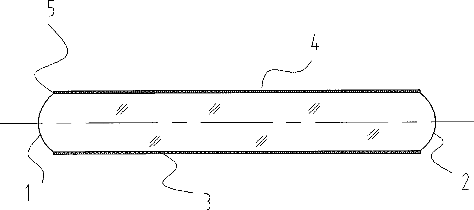
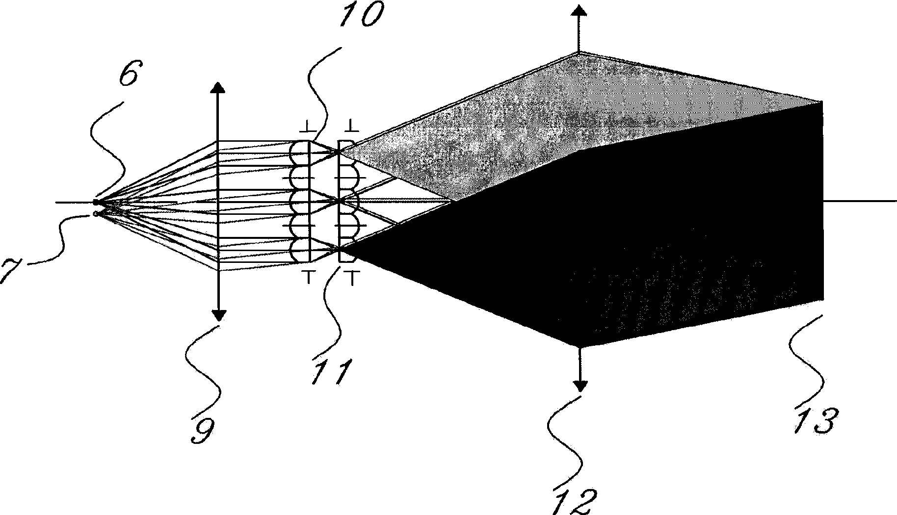
[0024] see figure 1 with figure 2 : figure 1 It is an external view of the microlens array of the present invention. figure 2 It is a sectional view of a microlens unit in the microlens array of the present invention. The microlens array includes at least two microlens units arranged in contact, and the microlens units are surrounded by a front working end surface 1, a rear working end surface 2 and side surfaces. In this embodiment, a microlens array with 6 rows and 8 columns is composed of 48 microlens units. see image 3 , the front working end surface 1 forms a first-level microlens array 10 , and the rear working end surface 2 forms a second-level microlens array 11 . The microlens unit is a rod. The cross-section of the rod-shaped body (that is, the aperture of the microlens unit) is polygonal or circular. In this embodiment, the cross section of...


PUM


Abstract

The invention relates to an optical lens, in particular to a microlens array. The invention discloses a microlens array which at least comprises two microlens units in contact arrangement. Each microlens unit consists of a front working end face, a back working end face and side faces. The front working end face forms a first-level microlens array; the back working end face forms a second-level microlens array; and all or part of the side faces of each microlens unit are coated by a light-absorbent dielectric layer. As the side faces of each microlens unit are coated with the light-absorbent dielectric layer capable of absorbing the misplaced off-axis stray light in an illuminated zone, the illumination evenness can be greatly improved. In addition, the structure coated with the light-absorbent dielectric layer can also reduce the diffraction effect of the microlens array, and consequently further improve the dodging effect. The light-absorbent dielectric layer also has a heat conducting action, and can evenly conduct out the energy of the absorbed stray light and prevent the device from failure caused by overheating.

Description

technical field [0001] The invention relates to an optical lens, in particular to a microlens array. Background technique [0002] Microlens array, also known as fly-eye lens or fly-eye lens, refers to an integral device composed of multiple small lenses integrated together through a certain mechanism. Often used in lighting systems, microlens arrays can homogenize light. A two-stage microlens array is usually used in combination to enhance the uniform light effect. [0003] see image 3 , is the working principle diagram of the microlens array. The light of the light source, including the on-axis point light source 6 and the small-angle off-axis point light source 7 allowed by the design, enters from the first-stage microlens array 10 composed of the front working end surface 1 of the microlens unit, and converges to the rear working end surface 2 Composition of the second-stage microlens array 11. That is, after the on-axis point light source 6 and the small-angle off-...

Claims


Application Information

Patent Timeline
Patent Type & Authority Applications(China)
IPC IPC(8): G02B3/00G02B1/10
Inventor 周松钻李仲禹黄玲
Owner SHANGHAI MICRO ELECTRONICS EQUIP (GRP) CO LTD
Why Eureka
Try Eureka