Fiber composite power cable

A power cable and optical fiber composite technology, which is applied in the direction of power cables, insulated cables, communication cables, etc., can solve problems such as optical transmission loss, and achieve the effect of preventing optical transmission loss

Inactive Publication Date: 2009-09-02
SHENYANG FURUKAWA CABLE +1
View PDF1 Cites 14 Cited by
  • Summary
  • Abstract
  • Description
  • Claims
  • Application Information

AI Technical Summary

Problems solved by technology

At this time, if the optical fiber is helically wound on the cable core, there are all around the cable core. For the underside of the metal sheath, the optical fiber is sandwiched between the cable core and the protruding part inside the corrugated shape, and the extrusion damage may occur, and light transmission may occur. loss

Method used


Image

  • Fiber composite power cable
  • Fiber composite power cable
  • Fiber composite power cable

Examples


Embodiment 1

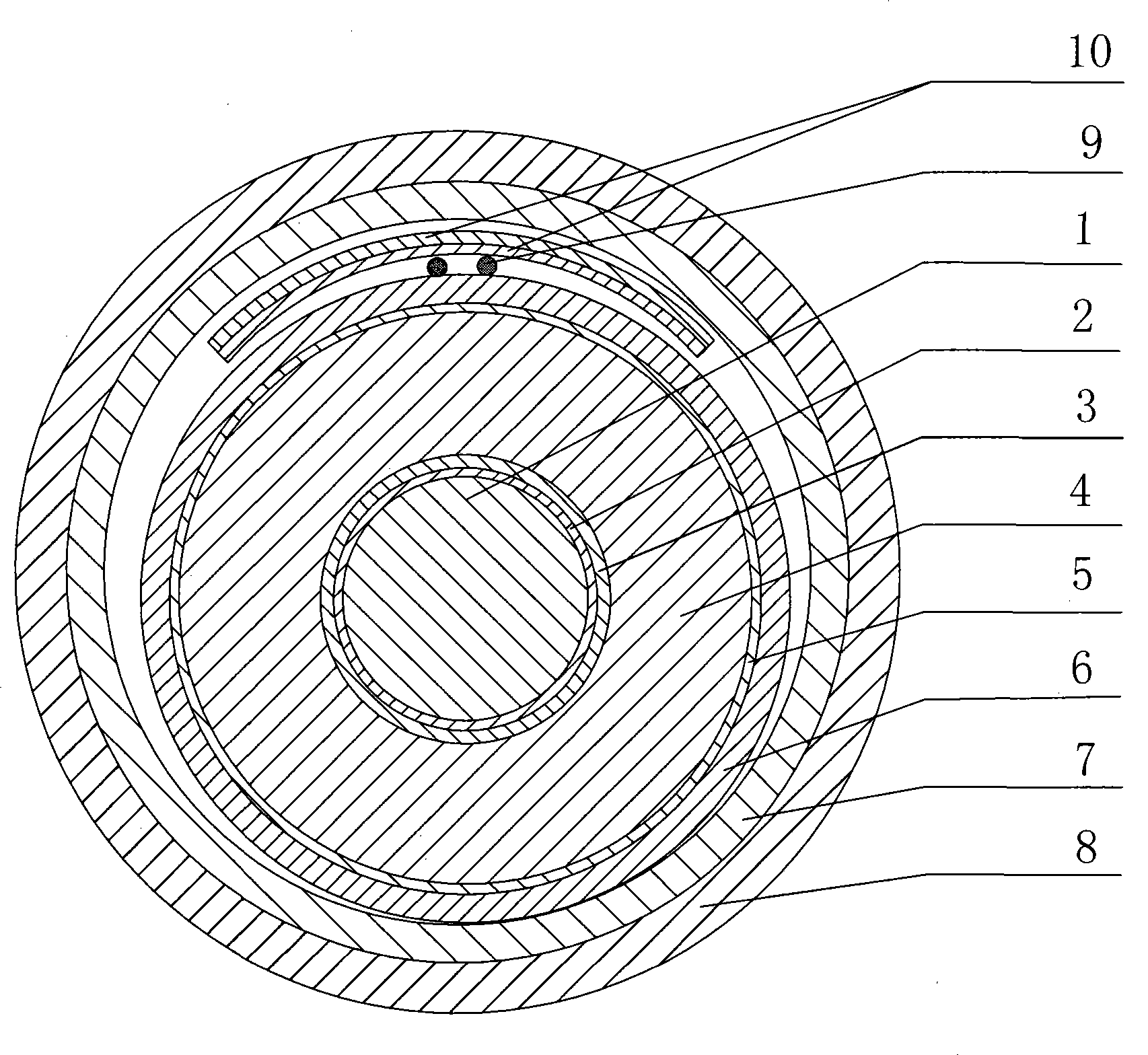
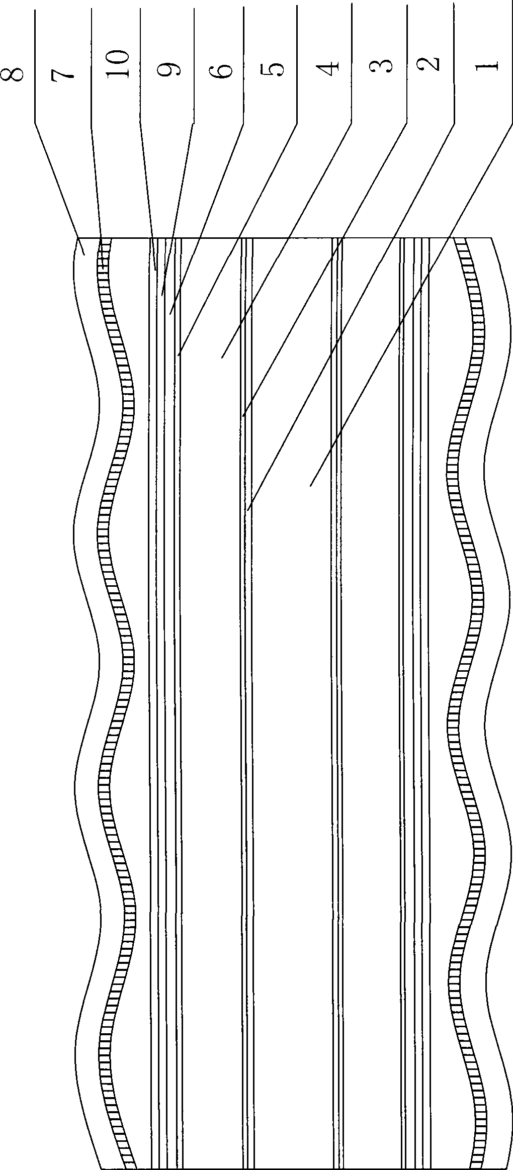
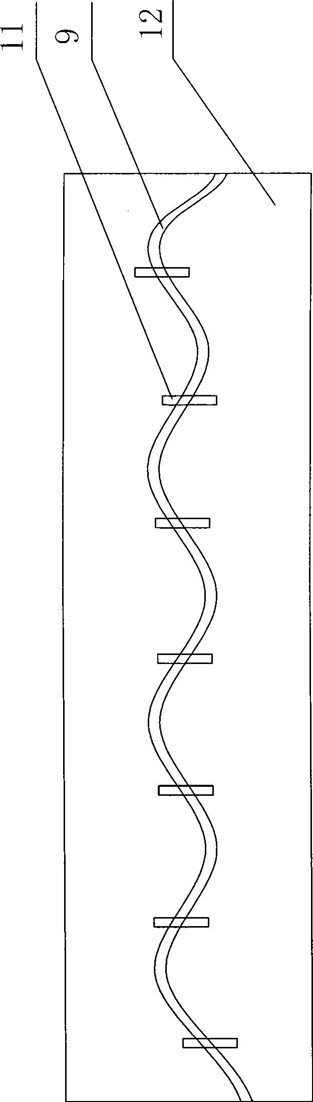
[0048] like Figure 1-Figure 3 As shown, in the optical fiber composite power cable of the present invention, the optical fiber is located between the cable core 12 and the sheath, and the optical fiber is placed on the cable core 12 in a serpentine shape along the length of the cable. The sheath includes a plastic sheath and a metal sheath, and a metal sheath formed in a spiral shape using aluminum or steel will be described below. The metal cable core 12 includes a cable conductor 1, a conductor semiconductive tape 2 covering the periphery of the cable conductor 1, an extruded semiconductive shielding layer 3 covering the periphery of the conductor semiconductive tape 2, and an extruded semiconductive shield covering the outer periphery of the conductor. XLPE (cross-linked polyethylene) insulating layer 4 on the periphery of layer 3, extruded insulating shielding layer 5 covering the periphery of XLPE (cross-linked polyethylene) insulating layer 4, and longitudinal water-blo...

Embodiment 2

[0072] The difference from Example 1 is:

[0073] like Figure 7 As shown, the shape of the metal sheath 7 in this embodiment can also be corrugated.


PUM


Abstract

The invention relates to a power cable of high-voltage cross-linking polyethylene insulated cable (CV cable) and the like, in particular to a fiber composite power cable. The fiber is arranged between a cable core and a sheath; and the fiber is arranged on the cable core in a snake-form along the length direction of the cable. The fiber of the power cable is arranged at a position closer to the cable conductor, thus measuring the core temperature of the cable precisely and preventing the optical transmission loss; and the fiber of the power cable is not warped when the power cable is bent or distorted.

Description

technical field [0001] The invention relates to power cables such as high-voltage cross-linked polyethylene insulated cables (CV cables), in particular to an optical fiber composite power cable. Background technique [0002] When the power cable is energized, it will generate heat due to the existence of resistance, and the cross-linked polyethylene as an insulator cannot be exposed to high temperature. The design temperature of the insulator is 90 degrees. If it exceeds this temperature, the conductor will move in the cable core (composed of conductor and insulator) due to polyethylene softening. Therefore, it is necessary to monitor whether the design value is exceeded by measuring the core temperature of the cable. At this time, since it is difficult to measure the temperature of the conductor, it is necessary to measure it at a point as close as possible to the conductor. Therefore, it is conceivable to place an optical fiber between the cable core and the sheath to me...

Claims


Application Information

Patent Timeline
IPC IPC(8): H01B9/00H01B11/22H01B7/17
Inventor 张道利丁皓郝钢王帅兵
Owner SHENYANG FURUKAWA CABLE
Why Eureka
Try Eureka