Improved structure of electrical connector

A technology for electrical connectors and improved structures, applied in the direction of connection, fixed connection, electrical components, etc., can solve problems such as complexity, increased manufacturing costs, and inconvenience, and achieve the effects of simplifying the manufacturing process, technological progress, and improving quality

Inactive Publication Date: 2009-09-02
MEGACEN INDAL
View PDF0 Cites 0 Cited by
  • Summary
  • Abstract
  • Description
  • Claims
  • Application Information

AI Technical Summary

Problems solved by technology

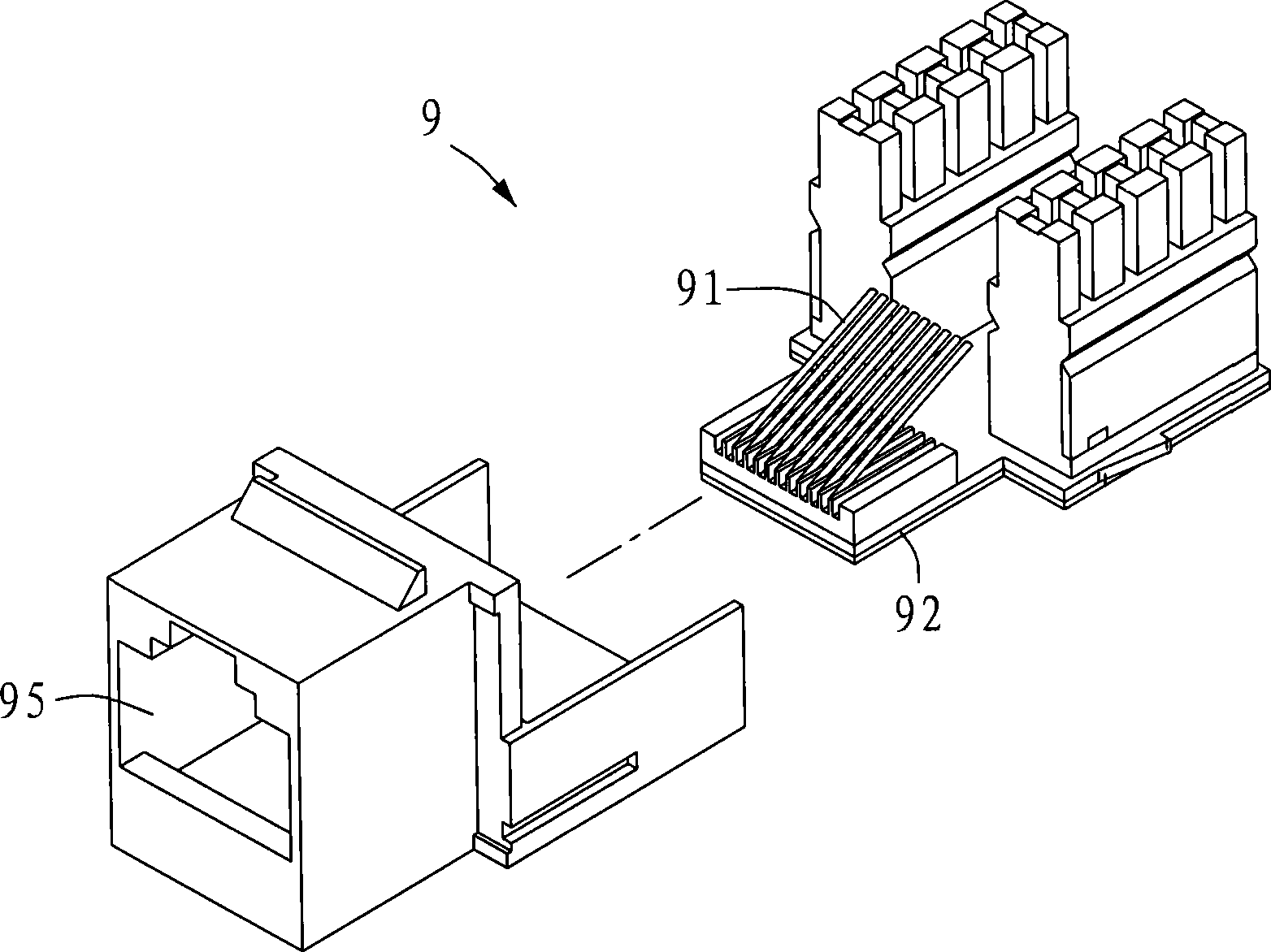
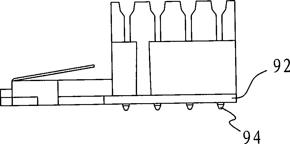
[0004] However, it can be clearly seen from the drawings that the general method of connecting the above-mentioned electrical conductive strips 91 to the circuit board 92 is to connect them by welding, and therefore produce solder joints 94 at the joints. In this way, in the manufacture of the electrical connector 9 One more process makes it more complicated, and relatively increases the manufacturing cost
In addition, the solder joints 94 (such as solder) connecting the electric conduction pieces 91 and the circuit board 92 are like the so-called dust impurities, which also have the problem of affecting the quality of signal transmission, so it is not very ideal.
[0005] It can be seen that the above-mentioned existing electrical connector obviously still has inconvenience and defects in structure and use, and needs to be further improved urgently.
In order to solve the above-mentioned problems, the relevant manufacturers have tried their best to find a solution, but no suitable design has been developed for a long time, and the general products do not have a suitable structure to solve the above-mentioned problems. This is obviously related. The problem that the industry is eager to solve

Method used


Image

  • Improved structure of electrical connector
  • Improved structure of electrical connector
  • Improved structure of electrical connector

Examples


Embodiment Construction

[0064] In order to further explain the technical means and effects of the present invention to achieve the intended purpose of the invention, the specific implementation, structure, characteristics and features of the improved structure of the electrical connector proposed according to the present invention will be described below in conjunction with the accompanying drawings and preferred embodiments. Efficacy, detailed as follows.

[0065] The aforementioned and other technical contents, features and effects of the present invention will be clearly presented in the following detailed description of preferred embodiments with reference to the drawings. Through the description of the specific implementation mode, when the technical means and effects adopted by the present invention to achieve the predetermined purpose can be obtained a deeper and more specific understanding, but the attached drawings are only for reference and description, and are not used to explain the presen...


PUM


Abstract

The invention relates to an improved structure of an electrical connector, which comprises the following components: a connector base, which comprises a connecting jack; an electrical conductive base, which comprises a plurality of electrical conductive shrapnels and is provided with a bent heave part; an electrical conductive module, which comprises complex electrical conductive elastic sheets and is provided with a bent protruded part; and a circuit board, which is provided with complex junction points and contact points, each junction point respectively corresponds to the heave part of the electrical conductive shrapnel, and each contact point respectively corresponds to the protruded part of the electrical conductive elastic sheet; the electrical conductive base, the electrical conductive module and the circuit board are respectively assembled on the connector base, a connecting part of the electrical conductive shrapnel is correspondingly exposed from the connecting jack, the heave part of the electrical conductive shrapnel is respectively and correspondingly butted against and contacted with each junction point of the circuit board with the elastic force, and each protruded part of the electrical conductive elastic sheet of the electrical conductive module is respectively and correspondingly butted against and contacted with each contact point of the circuit board with the elastic force. The improved structure of the electrical connector utilizes the connection way of elastic butting, thus avoiding various disadvantages which are caused by the welding way, simplifying manufacturing process and lowering cost, and simultaneously raising signal transmission quality.

Description

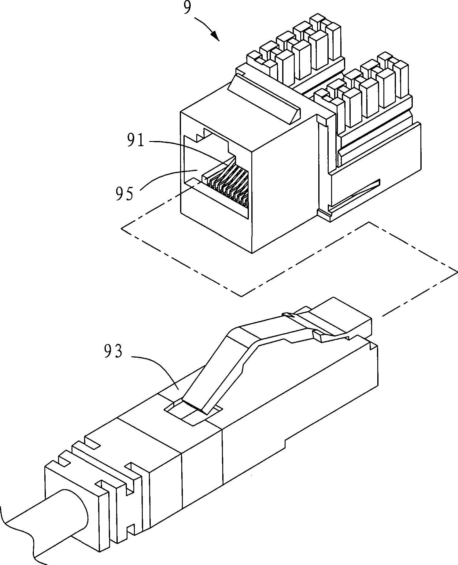
technical field [0001] The invention relates to an improved structure of an electrical connector, in particular to an improved structure of the electrical connector which can simplify the manufacturing process and reduce the cost while improving the quality of signal transmission. Background technique [0002] General electronic devices are equipped with electrical connectors for signal transmission in response to different signal connection requirements. For example, personal computers are equipped with electrical connectors that can provide network signal transmission to connect a The network cable can provide the function of network connection. [0003] Please also see figure 1 , figure 2 and image 3 as shown, figure 1 is an exploded perspective view of an existing known electrical connector, figure 2 is a perspective view of an existing known electrical connector, image 3 It is a cross-sectional view of an existing known electrical connector. The existing know...

Claims


Application Information

Patent Timeline
Patent Type & Authority Applications(China)
IPC IPC(8): H01R12/36H01R13/11H01R13/42H01R13/46H01R13/52H01R12/57
Inventor 何天赐
Owner MEGACEN INDAL
Why Eureka
Try Eureka