

Power supply circuit, module using same, motor drive apparatus and air conditioner
A technology of power supply circuit and power supply voltage, which is applied in the direction of AC motor control, output power conversion device, high-efficiency power electronic conversion, etc. It can solve the problems of air conditioner capacity reduction, large DC voltage change, and failure to maintain, etc., to achieve suppression of high-order Harmonic current, improved power factor, simple control effect
- Summary
- Abstract
- Description
- Claims
- Application Information
AI Technical Summary
Benefits of technology
Problems solved by technology
Method used
Image

Examples
Embodiment 1
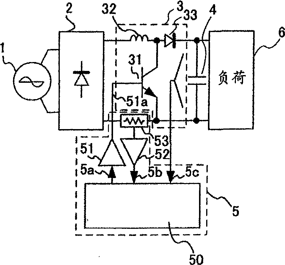
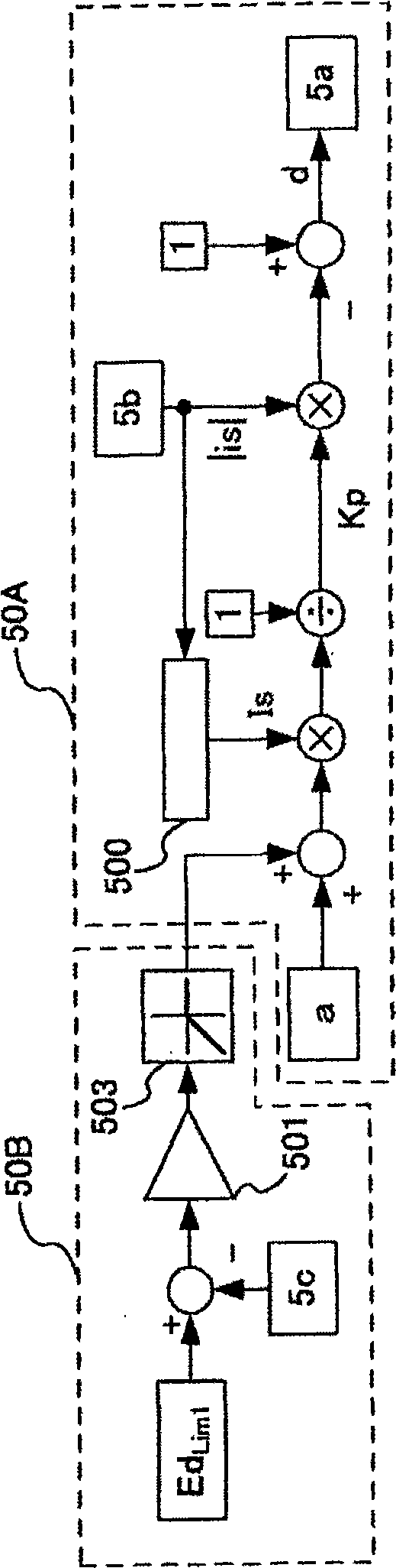
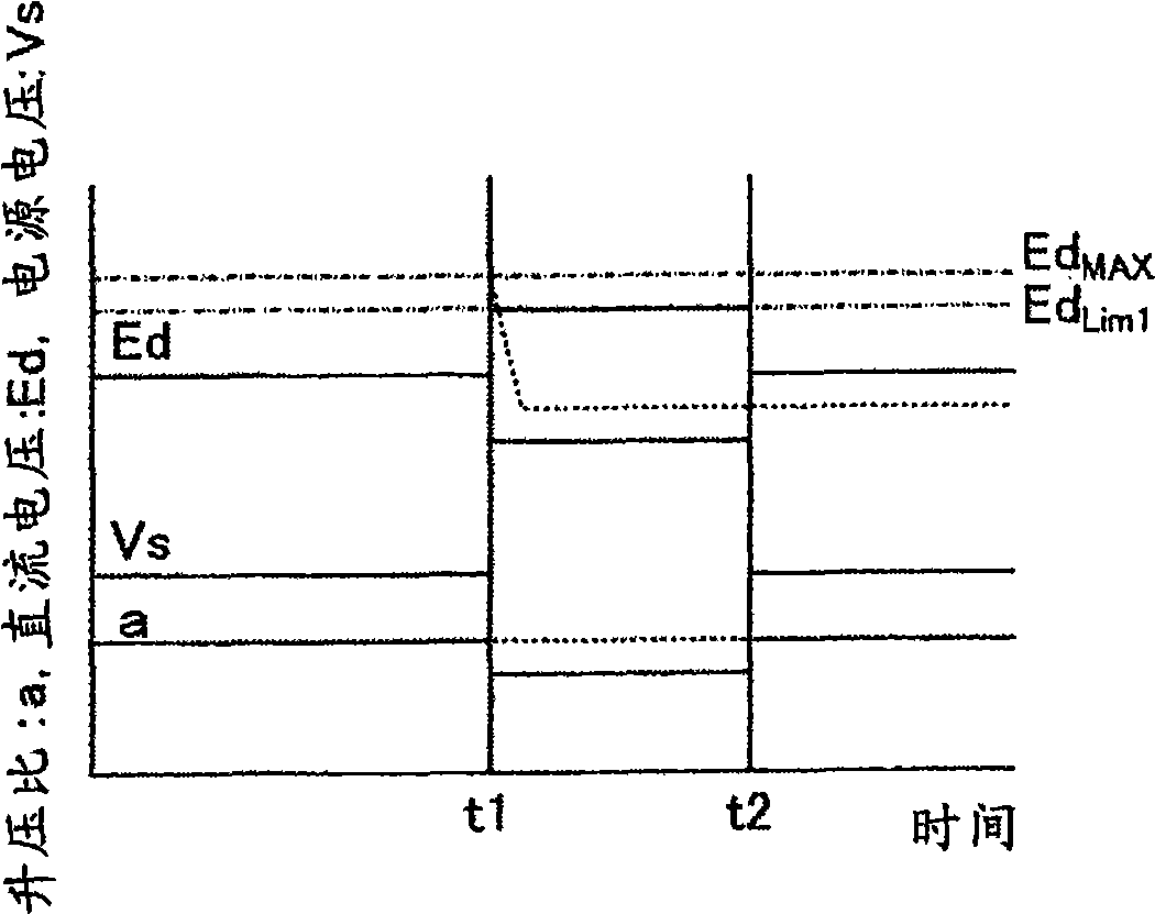
[0069] use Figure 1 to Figure 5 A first embodiment of the present invention will be described. figure 1 is an overall structural diagram of the power supply circuit of this embodiment, figure 2 is a control block diagram showing control content, image 3 , Figure 4 is an explanatory diagram of the operation of this embodiment, Figure 5 means to make figure 1 This is an overview diagram showing an example of usage of the control circuit that operates the power supply circuit.
[0070] use figure 1 Describe the structure and operation of the power supply circuit. This power supply circuit includes a rectifier circuit 2 connected to an AC power source 1 , a step-up chopper circuit 3 , a filter capacitor 4 , and a control circuit 5 , and supplies DC power to a load 6 connected to an output terminal of the filter capacitor 4 .
[0071] The step-up chopper circuit 3 includes a reactor 32 , a switching element 31 that short-circuits the AC power supply 1 through the reacto...
Embodiment 2
[0120] use Figure 6 to Figure 8 A second embodiment of the present invention will be described. The same symbols as those in the first embodiment represent the same operations, and description thereof will be omitted. Image 6 is the control block diagram of this embodiment, Figure 7 , Figure 8 It is an explanatory diagram of the operation of this embodiment. The overall circuit structure and figure 1 same.
[0121] Image 6 Like the first embodiment, it is composed of a boost ratio constant control unit 50A as a conventional technology and a boost ratio correction unit 50C as the present invention. The boost ratio correction unit 50C has the same configuration as the boost ratio correction unit 50B described in the first embodiment, and the only difference is the limit value Ed. Lim2 and limiter 504 . Furthermore, the proportional-integral compensator 502 performs the same figure 2 The shown proportional-integral compensator 501 operates in the same manner.
[0...
Embodiment 3
[0132] use Figure 9 to Figure 15 A third embodiment of the present invention will be described. The same symbols as in the first embodiment and the second embodiment represent the same operation, and description thereof will be omitted.
[0133] Figure 9 is an overall structural diagram of the motor drive device of this embodiment, Figure 10 is a control block diagram showing control content, Figure 11 , Figure 12 is an explanatory diagram of the operation of this embodiment, Figure 13 , Figure 14 is the input current waveform flowing into the power supply circuit, Figure 15 It is a module external view showing an example of the usage form of this embodiment.
[0134] Figure 9 It shows that a motor driving circuit composed of a motor 9 and an inverter circuit 8 is connected as a load of the power supply circuit of the present invention, and the control circuit of the power supply circuit of the present invention and the control circuit of the inverter circuit 8 ...
PUM
 Abstract
Description
Claims
Application Information