
Multi-lens optical center superposing type omnibearing shooting device and panoramic shooting and retransmitting method

An omnidirectional camera and multi-lens technology, which is applied to broadcast devices, video cameras, multi-lens optical center coincidence omnidirectional camera devices, panoramic cameras, and broadcast fields, can solve the problems of different software processing, difficult to achieve, and a large workload.

Active Publication Date: 2009-09-02
BEIJING WEIKAI SAIDE TECH DEV CO LTD
View PDF1 Cites 77 Cited by
  • Summary
  • Abstract
  • Description
  • Claims
  • Application Information

AI Technical Summary

Problems solved by technology

However, the compound-eye omni-directional camera device also has certain defects: First, when multiple cameras are combined into a compound-eye omni-directional camera device, there will be video blind spots due to the intersection of optical paths. , resulting in a large workload
Second, the method of video transmission also has defects: all-round video information (360 degrees by splicing 4-8 images or 180 degrees by splicing 2-4 images)
However, the completion of the above functions requires high video compression, transmission rate and network bandwidth.
Therefore, due to the defects in the process of realizing panoramic camera and broadcasting of the utility model patent (Patent No.: ZL00245946.9) of the compound-eye omnidirectional camera device applied by the applicant on July 28, 2000, many occasions such as low network bandwidth difficult to achieve

Method used


Image

  • Multi-lens optical center superposing type omnibearing shooting device and panoramic shooting and retransmitting method
  • Multi-lens optical center superposing type omnibearing shooting device and panoramic shooting and retransmitting method
  • Multi-lens optical center superposing type omnibearing shooting device and panoramic shooting and retransmitting method

Examples


Embodiment Construction

[0054] Specific embodiments will be described in detail with reference to the accompanying drawings.

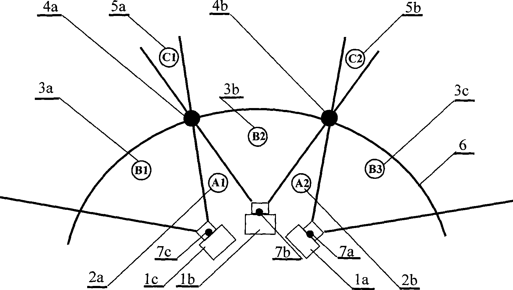
[0055] figure 1 The field of view formed by the video image optical path cross camera group (the schematic diagram of the video image optical path of the compound eye omnidirectional camera device patent applied by the applicant in 2000);

[0056] In the figure, three cameras are taken as an example: 1a, 1b, and 1c constitute a part of the camera group, and are deployed with a point as the center of the circle, evenly placed on a circle with the same radius as the center of the circle, and each camera is responsible for shooting 360 degrees or 180 degrees An angle in the field of view in degrees (the angle depends on the angle of view of the camera lens). The video images collected by the camera group can be combined into a complete 360-degree or 180-degree on-site omnidirectional video image. 2a in the figure is the blind area A1 existing in the optical path of the video i...


PUM


Abstract

The invention relates to a multi-lens optical center superposing type omnibearing shooting device and a panoramic shooting and retransmitting method. A special optical path design is adopted to superpose the optical centers (comprising practical optical centers and virtual optical centers) of video cameras in different directions and eliminate the defects caused by optical path cross; meanwhile, images in global, semiglobular or circular regions are collected so that the information of video images in different depths of field can be well connected to form an integral omnibearing image. A user playing the video images at a client can select a needed view by moving a mouse, a rocker or a remote control, i.e., uplink data to be sent to a video server is changed. The video server cuts the generated panoramic video into different contents and sends the contents to corresponding clients according the requirements of the clients so that different users can freely view interested regions without mutual influence, the function for spectators at the clients to personally select fields of view is realized, and the spectators can glance to the left and to the right to have an immersed sense.

Description

Technical field [0001] The invention relates to a set of camera and broadcasting devices and methods, in particular to a group of multi-lens optical center coincident omni-directional camera devices and methods for panoramic shooting and broadcasting, belonging to the field of video surveillance and video broadcasting. Background technique [0002] Now let’s explain the camera monitoring equipment used in the field of security protection: After investigation and consulting information, the camera part of the commonly used security monitoring system at present, such as: German Bosch VG4300 series high-speed dome camera, American Nuctech VC-881 high-speed dome camera Cameras and YUCOO-NC7201 network cameras of Guangzhou Youke Video Equipment Co., Ltd. and other monitoring devices can not only be used for regional monitoring based on computer local area networks, such as traditional monitoring of residential quarters, office buildings, banks, shopping malls, etc.; In cross-regi...

Claims


Application Information

Patent Timeline
IPC IPC(8): H04N5/225H04N7/18G03B37/00
Inventor 王广生
Owner BEIJING WEIKAI SAIDE TECH DEV CO LTD
Learn More