Rolling mill and method for controlling a rolling mill

A technology of rolling equipment and rolling stands, applied in metal rolling, tension/pressure control, braking/tightening devices, etc., to achieve the effect of improving the introduction of tension, uniform tension, and improving controllability and stability

Inactive Publication Date: 2011-09-07
PRIMETALS TECH GERMANY
View PDF2 Cites 0 Cited by
  • Summary
  • Abstract
  • Description
  • Claims
  • Application Information

AI Technical Summary

Problems solved by technology

These methods are likewise often limited in existing plants, which are limited by struct

Method used


Image

  • Rolling mill and method for controlling a rolling mill
  • Rolling mill and method for controlling a rolling mill
  • Rolling mill and method for controlling a rolling mill

Examples


Embodiment Construction

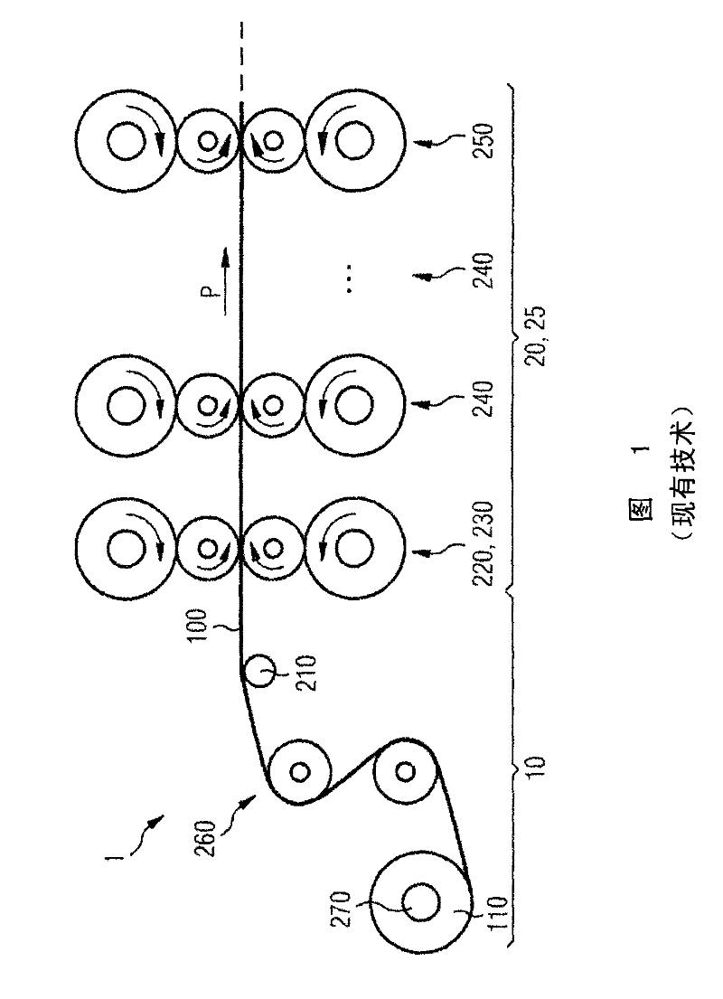
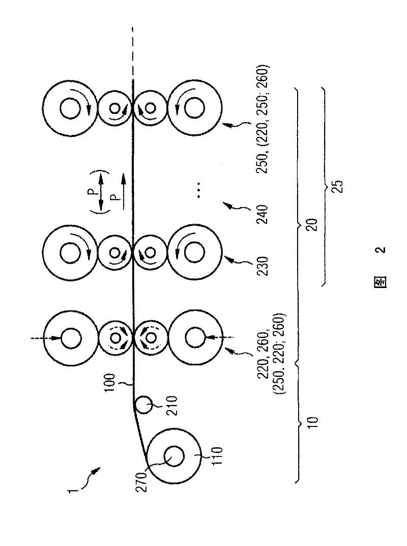
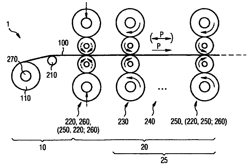
[0026] The following exemplary embodiment relates to a tandem cold strip rolling plant with a metal strip introduction section 10 constructed according to the invention and a tandem rolling train 20 constructed according to the invention. In particular, the tandem rolling train 20 is driven or controlled differently from the prior art, which affects the strip introduction section 10 of the tandem cold strip rolling installation 1 . That is, the package 260 ( FIG. 1 ) having the function of increasing the tension of the strip is not required inside the strip introduction section 10 . However, the invention is not restricted to a tandem cold strip rolling plant 1 , but rather relates to a tandem mill train 20 in general. The tandem rolling train 20 here is a rolling stand arrangement which consists of at least two rolling stands 220 , 230 , 240 , 250 connected in series, preferably directly in series, in the production direction P of the metal strip 100 . That is, the present i...


PUM


Abstract

The invention relates to a rolling mill, in particular, a cold strip tandem rolling mill (1), for producing a metal strip (100), with a number of stands (220, 260; 230; 240;...; 250) arranged in a tanThe invention relates to a rolling mill, in particular, a cold strip tandem rolling mill (1), for producing a metal strip (100), with a number of stands (220, 260; 230; 240;...; 250) arranged in a tandem path (20), wherein, in a direction of production (P) of the metal strip (100), a first stand (220) is designed as driving stand (220, 260) and serves as inlet for a section (25) of the tandem pathdem path (20), wherein, in a direction of production (P) of the metal strip (100), a first stand (220) is designed as driving stand (220, 260) and serves as inlet for a section (25) of the tandem path (20), in which a primary thickness reduction of the metal strip (100) occurs, and by corresponding control of the driving stand (220, 260), an increase in the mechanical inlet tension of the metal st(20), in which a primary thickness reduction of the metal strip (100) occurs, and by corresponding control of the driving stand (220, 260), an increase in the mechanical inlet tension of the metal strip (100) can be achieved. The invention further relates to a method for controlling a rolling mill, in particular, a cold strip tandem rolling mill (1), for producing a metal strip (100), wherein, inrip (100) can be achieved. The invention further relates to a method for controlling a rolling mill, in particular, a cold strip tandem rolling mill (1), for producing a metal strip (100), wherein, in a production direction (P) of the metal strip (100), a first stand (220) is controlled as driving stand (220, 260), said driving stand (220, 260) achieving a significant increase in the mechanical ina production direction (P) of the metal strip (100), a first stand (220) is controlled as driving stand (220, 260), said driving stand (220, 260) achieving a significant increase in the mechanical inlet tension on the metal strip (100) and a significant thickness reduction of the metal strip (100).let tension on the metal strip (100) and a significant thickness reduction of the metal strip (100).

Description

technical field [0001] The invention relates to a rolling plant, in particular a tandem cold strip rolling plant, and a method for controlling such a rolling plant. The invention also relates to the use of the first stand of a rolling plant, in particular a tandem cold strip rolling plant. Background technique [0002] In rolling plants, especially in tandem cold strip rolling plants, the aim when distributing pass reductions is that, in addition to distributing pass reductions for technical reasons, it is also possible to correspond to individual The structural state of the rolling stand distributes the pass reduction in order to make optimum use of this distribution in terms of production. [0003] In discontinuous tandem mill trains, not only longitudinally separated hot strips are used as feed material, but also strips from the box furnace annealing process, which are wound with a slight strip tension due to process conditions Coil, so it may appear that the first stan...

Claims


Application Information

Patent Timeline
IPC IPC(8): B21B37/48B21B39/08
CPCB21B37/48B21B39/08B21B1/24
Inventor B·博塔
Owner PRIMETALS TECH GERMANY
Why Eureka
Try Eureka