Rotator for motor and method for manufacturing the same

A technology of motors and rotors, applied in the field of motor rotors and its manufacturing, can solve problems such as resin damage, and achieve the effect of preventing peeling or cracks

Inactive Publication Date: 2009-09-02
SANYO DENKI CO LTD
View PDF0 Cites 18 Cited by
  • Summary
  • Abstract
  • Description
  • Claims
  • Application Information

AI Technical Summary

Problems solved by technology

Therefore, when a centrifugal force is applied to the resin impregnated in the wire winding layer in the direction of the void, the resin may be broken

Method used


Image

  • Rotator for motor and method for manufacturing the same
  • Rotator for motor and method for manufacturing the same
  • Rotator for motor and method for manufacturing the same

Examples


Embodiment Construction

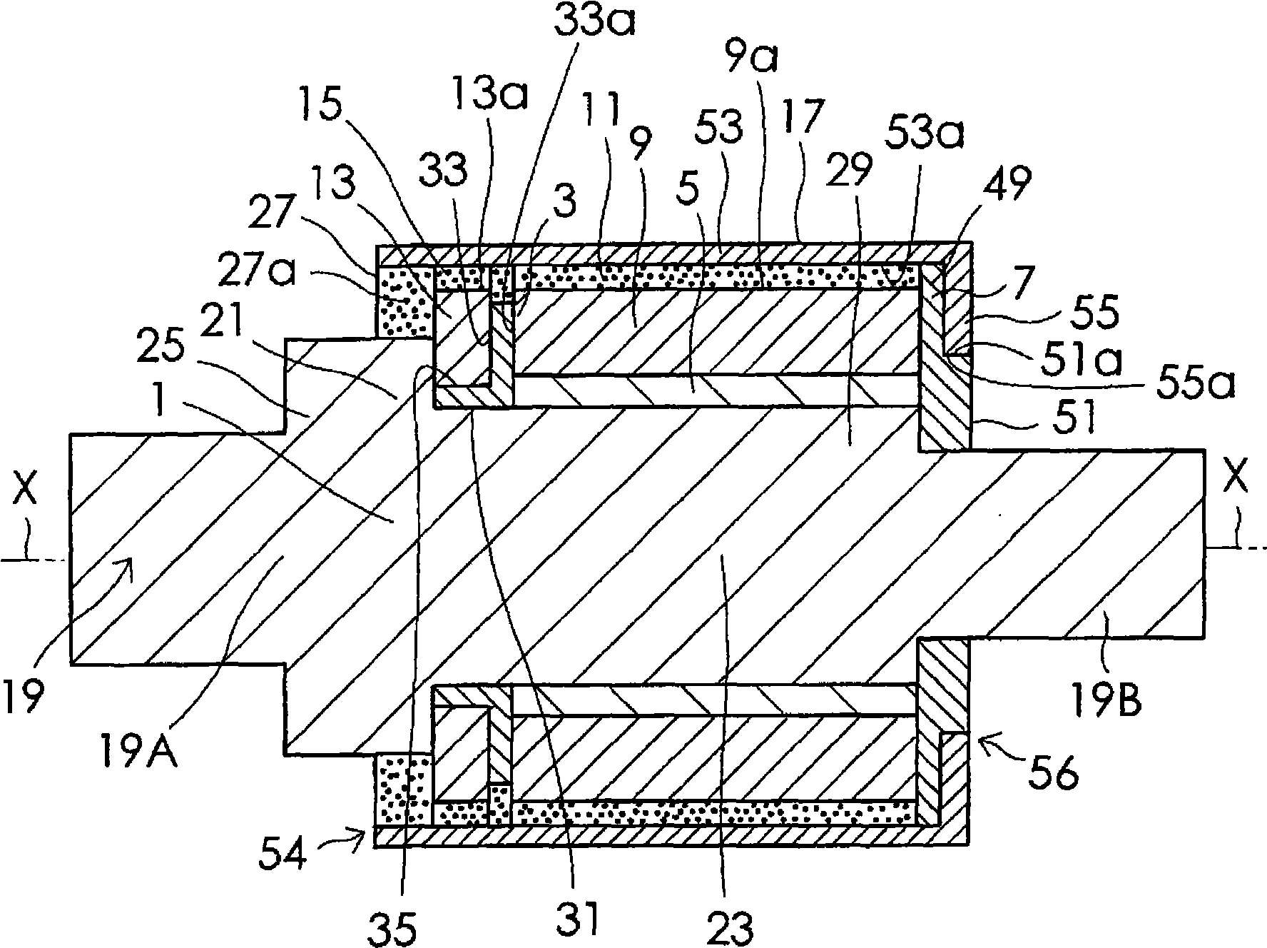
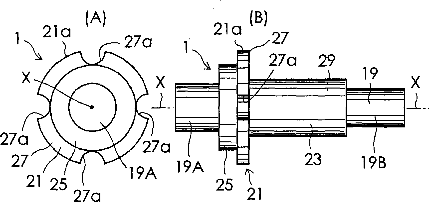
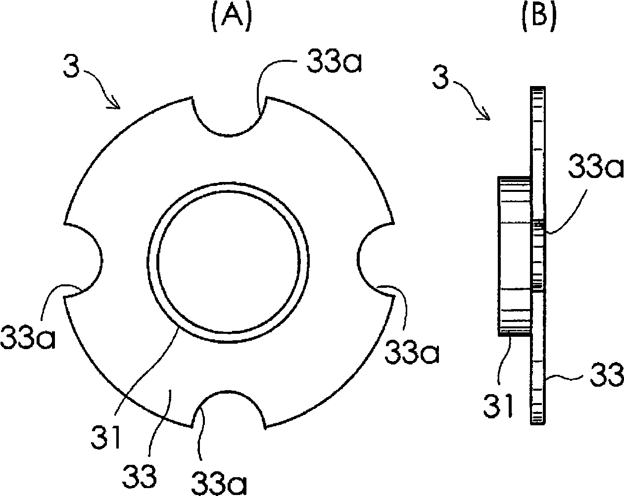
[0036] Hereinafter, embodiments of the present invention will be described in detail with reference to the drawings. figure 1 It is a cross-sectional view of a rotor for an electric motor according to an embodiment of the present invention used in a high-speed rotating electric motor rotating at a high speed of 150,000 rpm or more. figure 2 (A) and (B) are the front view and the right side view of the rotating shaft structure used for the motor rotor of this example. like figure 1 As shown, the motor rotor of this example has: a rotating shaft structure 1, a partition member 3, a permanent magnet layer 5, a second annular member 7, a wire winding layer 9, a resin layer 11, a continuous wire winding layer 13, a resin layer Extension part 15, cylinder body 17. The rotating shaft structure 1 includes the rotating shaft 19 of the present invention, and is made of martensitic stainless steel in this example. like figure 2 As shown in (A) and (B), the rotating shaft structure ...


PUM


Abstract

The invention provides a rotator for a motor, which, even when rotated at a high speed, can prevent breakage of a resin impregnated into a yarn winding layer. A yarn formed of a reinforcing fiber material is wound on a permanent magnet layer (5) to such an extent that a space is formed between a yarn winding layer (9) on its outer peripheral face (9a) and a cylindrical body (53) on its inner peripheral face (53a), whereby the yarn winding layer (9) is formed. A curable resin is impregnated into the yarn winding layer (9). A continuous yarn continuous to the yarn constituting the yarn winding layer (9) is placed within an annular passage (35) through a yarn passage recess part (33a) and is wound at a high level of tension on the bottom of the passage (35) to form a continuous yarn winding layer (13). A curable resin is impregnated into the continuous yarn winding layer (13). A cylinder (17) is mounted on the first and second annular members (21, 7) by shrink fitting. A curable resin is filled into a space between the yarn winding layer (9) on its outer peripheral face (9a) and the cylindrical body (53) on its inner peripheral face (53a) through a resin filling passage (27a) and the yarn passage recess part (33a). A curable resin is filled into a space between the continuous yarn winding layer (13) on its outer peripheral face (13a) and the cylindrical body (53) on its inner peripheral face (53a) through the resin filling passage (27a). Air bubbles contained in the curable resin is deaerated through the resin filling passage (27a) and the yarn passage recess part (33a), followed by heating to cure the resin.

Description

technical field [0001] The present invention relates to a rotor for an electric motor and a manufacturing method thereof. Background technique [0002] Generally, a rotor for an electric motor includes a magnet mounting portion provided on a rotating shaft, and a permanent magnet layer configured by arranging a plurality of permanent magnets on the surface of the magnet mounting portion. However, when the motor rotor rotates at high speed, many permanent magnets may be damaged due to centrifugal force. Then, as described in (Japanese) Patent No. 2847756, a rotor for an electric motor is proposed, which includes: a wire winding layer formed by winding a wire made of a reinforcing fiber material on a permanent magnet layer; The first and second annular members on both sides in the axial direction of the magnet mounting portion, and the cylindrical body fixed to the first and second annular members and contacting and covering the surface of the wire winding layer. Furthermore...

Claims


Application Information

Patent Timeline
Patent Type & Authority Applications(China)
IPC IPC(8): H02K1/27H02K15/02
CPCH02K15/03H02K1/2753Y10T29/49012Y10T29/49009H02K5/128H02K15/02H02K1/27
Inventor 宫下利仁松下孝田中宪仁
Owner SANYO DENKI CO LTD
Why Eureka
Try Eureka